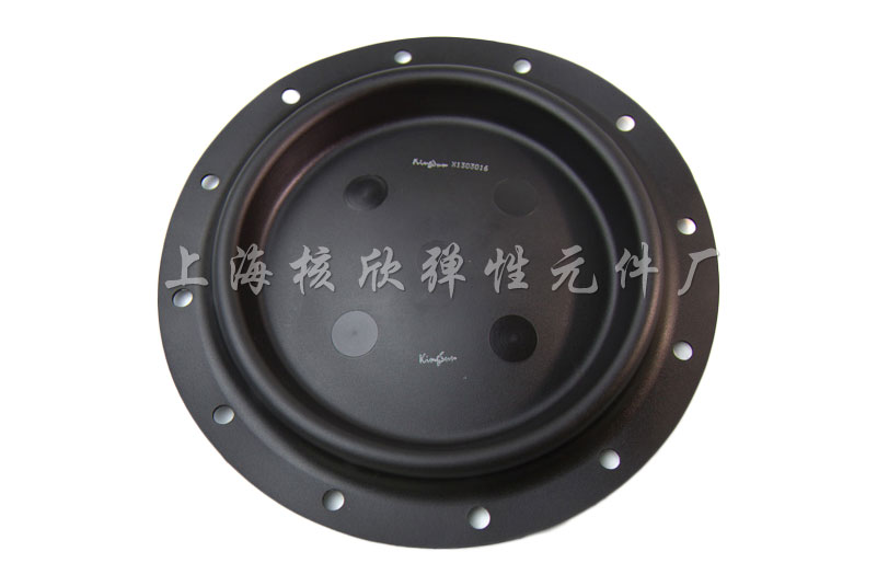
Fig.3. A typical piston rubber film (edge can be fixed with bolts)
Typical piston rubber films in a pneumatic brake device that is commonly used in drilling operations are shown in Fig.1-Fig.3. When the brake device is activated, the piston rubber film deforms under increasing air pressure and pushes the brake lever forward to achieve braking.

Fig.4. The cross section of the rubber film.
Some features of this problem:
- The rubber film is an axisymmetric structure.
- The hyperelastic behavior of rubber material means large deflection should be turned on. Mooney-Rivlin material model is used.
- Both displacement boundary conditions and stress boundary conditions are involved. More details can be found in the following APDL.
FINISH/CLEAR!*************************************!units: m, N, Pa!define parameters!*************************************ADD_R=0.005 !the increased radius of the central partEDGE_R=0.151+ADD_R !the radius of the edgeOUT_R=0.1+ADD_R !the outer radius of the central partIN_R=0.06+ADD_R !the inner radius of the central partR_HOLE=0.02 !the radiu of the central holeH_RIDGE=0.05 !heightTHICK=0.008 !thicknessRR_RIDGE=0.006 !the radius of fillet 1RR_IN=0.018 !the radius of fillet 2PI=2*ASIN(1)F_ANTI=11300 !the force that is exerted on the rubber film by brake leverPRES_UP=0.637E6 !the braking air pressure!*************************************WID_EDGE=EDGE_R-OUT_RWID_CAP=IN_R-R_HOLER_RIDGE=(OUT_R+IN_R)/2WID_RIDGE=(OUT_R-IN_R)/2THETA=ATAN((H_RIDGE-THICK)/WID_RIDGE)THIN=THICK/COS(THETA)DELTA=THICK*TAN(PI/2-THETA)KYY=-H_RIDGE-THICK/2-((RR_RIDGE+THICK/2)/SIN(PI/2-THETA)-(RR_RIDGE+THICK/2))!*************************************!create geometry!*************************************/PREP7K,1,0,-THICK/2,0K,2,0,-THICK/2,0K,3,RR_IN,-THICK/2,0K,4,R_RIDGE,KYY,0K,5,OUT_R,0,0K,6,EDGE_R,0,0LSTR,2,3 !define a straight lineLSTR,3,4LSTR,4,5LSTR,5,6LFILLT,1,2,RR_IN-THICK/2 !generates a fillet line between two intersecting linesLFILLT,2,3,RR_RIDGE+THICK/2LFILLT,4,3,RR_IN-THICK/2KL,6,0.5,101 !generate a keypoint at a specified location on an existing lineK,13,0,0,0K,14,0,-THICK/2,0LSTR,13,14FLST,8,7,4 !http://www.ansysjgy.com/index.php/2021/07/12/fa6c797878/FITEM,8,1FITEM,8,5FITEM,8,2FITEM,8,6FITEM,8,3FITEM,8,7FITEM,8,4ADRAG,8,,,,,,P51X !drag line8 along the path defined by line 1,5,2,6,3,7,4!*************************************!define element and material property!*************************************ET,1,HYPER56 !2D 4-node mixed U-P hyperelastic solid element !http://research.me.udel.edu/~lwang/teaching/MEx81/ansys56manual.pdf !https://www.wenjiangs.com/doc/0aqjwbuqKEYOPT,1,3,1 !axisymmetricMP,EX,1,3.25E6MP,NUXY,1,0.49967TB,MOONEY,1TBDATA,1,1.6E6 !yield strengthTBDATA,2,0.81E6 !shear modulusR_DOWN=KX(16)PRES_DOWN=F_ANTI/(PI*R_DOWN**2) !calculate the stress from the brake lever!*************************************!mesh!*************************************AESIZE,ALL,0.002MSHAPE,0,2DMSHKEY,1AMESH,ALLFINISH/SOLU!*************************************!displacement BCs!*************************************DL,8,,SYMM !symmetric boundaryDA,7,ALL !the area fixed by boltsDA,1,UXASEL,S,AREA,,1,,NSLA,S,1CP,1,UY,ALL !couple the y-deformation of all nodes on area 1(because of the prensence of braking rod)CPSGEN,1,UY !generates sets of coupled nodes from existing setsALLSEL!*************************************!stress BCs!*************************************LSEL,S,LINE,,10,25,3SFL,ALL,PRES,PRES_UP !apply braking are pressureALLSELSFL,11,PRES,PRES_DOWN !apply the stress from braking rodLSEL,S,LINE,,14,26,3SFL,ALL,PRES,0.1E6 !apply atmospheric pressureALLSELANTYPE,0NLGEOM,1 !turn on large deflectionNSUBST,5,0,0OUTRES,,1SOLVE/POST1PLNSOL,S,EQV,2,1


Fig.7. Area number.
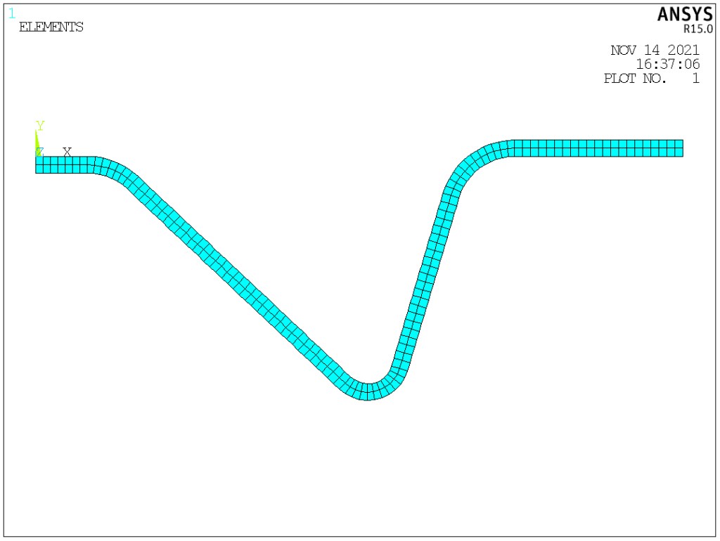
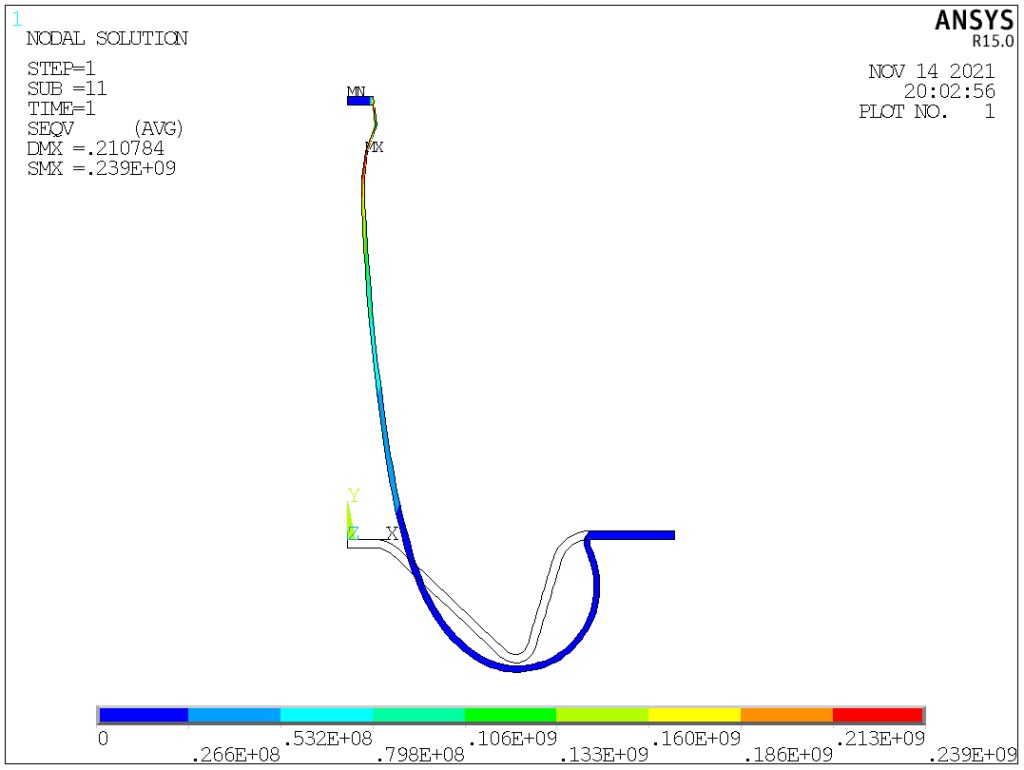
Fig.8. Discretization.