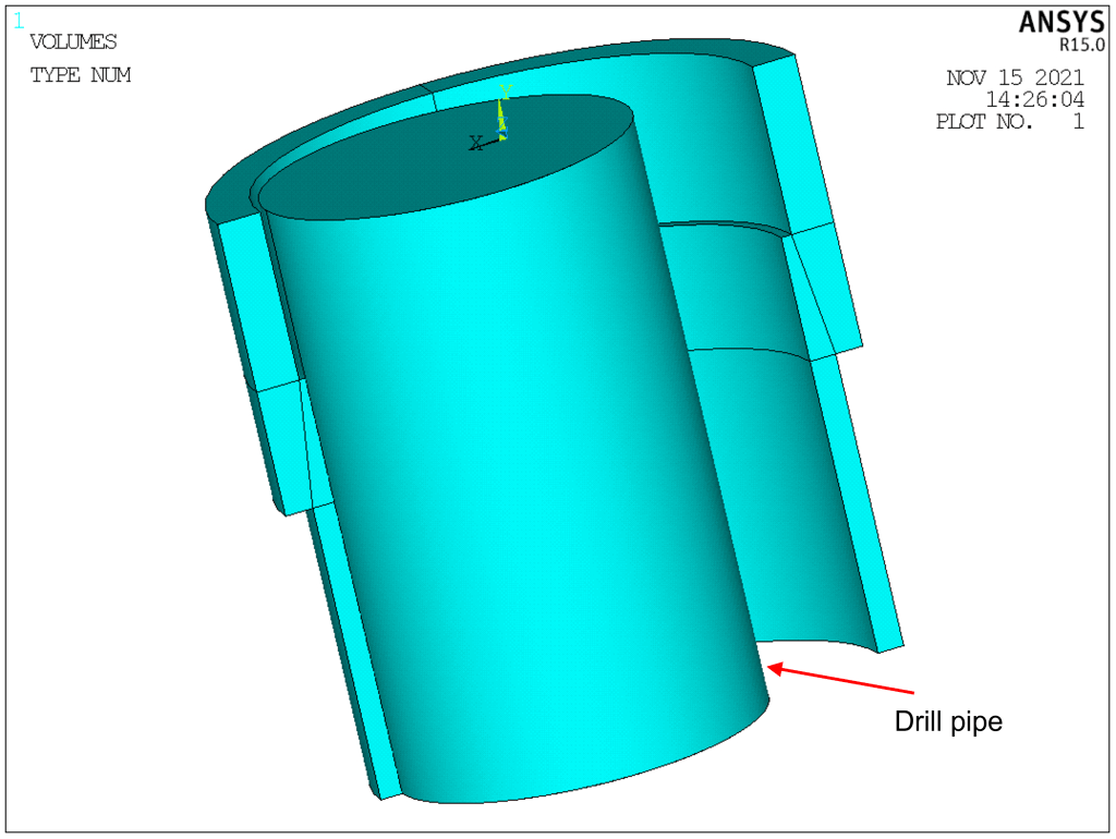
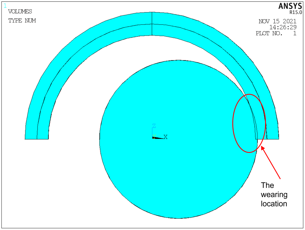
Because the reciprocating and rotary motion of the drill pipe in the casing is eccentric, the radial and axial friction between the drill pipe and the casing causes serious wear on the outer surface of the drill pipe and the inner surface of the casing. This wear mostly occurs at the joint of the drill pipe and the casing.
Some features of this model:
- Axisymmetric structure. Volume can be generated by rotating area.
- To create the thickness reduction. Boolean operation (volume subtraction) can be applied.
- Thread can be ignored.
- Material is assumed isotropic and homogeneous.


FINISH
/CLEAR
/PREP7
*SET,IN_M,0.0254 !convert inch to meter
!*************************
!the parameters of drill pipe
!*************************
*SET,RDRILL,0.084 !radius (unit: m)
*SET,DELTA,0.002 !the wearing thickness
!*************************
!loads on the casing
!*************************
*SET,PRESSIN,40E6 !inner pressure (unit: Pa)
*SET,DRAGPRESS,100E6 !
!*************************
!the parameters of casing coupling
!*************************
*SET,NL,10.625*IN_M
*SET,L4,4.512*IN_M
*SET,W,10.625*IN_M
*SET,D,9.625*IN_M
*SET,T,0.472*IN_M
*SET,TANGENT,1/16
!*************************
!the parameters of model
!*************************
*SET,RCAS_OUT,D/2 !outer radius of casing
*SET,RCAS_IN,D/2-T !inner radius of casing
*SET,RCOUP_OUT,W/2 !outer radius of coupling
*SET,RCOUP_IN,RCAS_OUT-L4*TANGENT !inner radius of coupling
*SET,LCOUP_UP,(NL-L4)/2 !upper length of coupling
*SET,LCOUP,NL/2 !length of coupling
*SET,LALL,NL !
*SET,ECCENDIS,RCAS_IN-RDRILL+DELTA
!*************************
!define element type and material properties
!*************************
ET,1,SOLID95
MP,EX,1,2.1E11
MP,PRXY,1,0.3
!*************************
!create geometry
!*************************
K,1,RCOUP_IN,0
K,2,RCOUP_OUT,0
K,3,RCOUP_OUT,-LCOUP_UP,0
K,4,RCOUP_IN,-LCOUP_UP,0
K,5,RCAS_IN,-LCOUP_UP,0
K,6,RCOUP_OUT,-LCOUP,0
K,7,RCAS_OUT,-LCOUP,0
K,8,RCAS_IN,-LCOUP,0
K,9,RCAS_OUT,-LALL,0
K,10,RCAS_IN,-LALL,0
K,11,
K,12,0,-LALL,0
A,4,3,2,1
A,7,6,3,4
A,8,7,4,5
A,10,9,7,8
VROTAT,1,2,3,4,,,11,12,180
WPROT,,90
CYL4,ECCENDIS,0,RDRILL,,,,LALL
NUMCMP,ALL
VSEL,S,,,3,4,1
CM,V_OUT,VOLU
ALLSEL
BTOL,5E-4
VSBV,V_OUT,9
ALLSEL
!*************************
!mesh
!*************************
SMRT,4
ESIZE,0.006
VSWEEP,ALL
NUMCMP,ALL
FINISH
WPCSYS
!*************************
!BCs
!*************************
/SOLU
ASEL,S,LOC,Z,0
DA,ALL,SYMM
ALLSEL
ASEL,S,LOC,Y,0
DA,ALL,SYMM
ALLSEL
!*************************
!analyze the resistance to inner pressure
!*************************
*CREATE,PRESS_IN
ASEL,S,LOC,Y,-LALL
DA,ALL,SYMM
ALLSEL
NSEL,S,,,15401
D,ALL,UX !additional constraint to eliminate error
ALLSEL
CSYS,5
ASEL,S,LOC,X,RCAS_IN
ASEL,A,LOC,X,RCOUP_IN
ASEL,A,AREA,,25,35,10
ASEL,A,AREA,,34,39,5
SFA,ALL,,PRES,PRESSIN
ALLSEL
CSYS,0
SOLVE
*END
!*************************
!tensile analysis
!*************************
*CREATE,AXIAL_DRAG
ASEL,S,LOC,Y,-LALL
SFA,ALL,,PRES,-DRAGPRESS
ALLSEL
NSEL,S,,,15401
D,ALL,UX !additional constraint to eliminate error
ALLSEL
SOLVE
*END
!*************************
!run either one
!*************************
!*USE,AXIAL_DRAG
*USE,PRESS_IN
FINISH
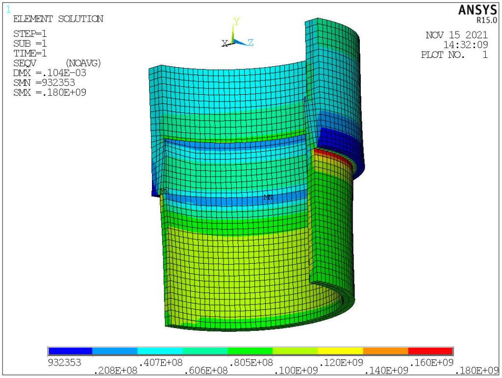
/POST1
PLESOL, S,EQV, 0,1.0