A reinforced concrete slab can be strengthened by adhering carbon fiber sheets to the tension side. This is a common practice in concrete structure reinforcement (as shown in Fig.1)
Fig.1. Carbon fiber reinforcement.
In this problem, the reinforced concrete slab is simply supported. A carbon fiber sheet is attached to the lower surface of the slab.
Some features of the problem:
1. Material Model
The stress-strain curve of concrete:

Fig. 2. Multilinear kinematic hardening.
The stress-strain curve of rebar:
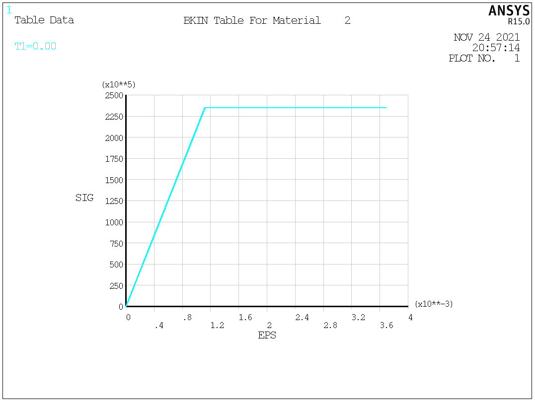
Fig. 3. Bilinear kinematic hardening.
Carbon fiber is considered as a linear elastic material throughout the analysis.
2. Elements
Concrete: SOLID65 element. This element is specifically designed for concrete.
Rebar: LINK8 element.
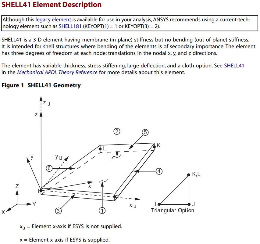
Carbon fiber sheet: SHELL41 element.
3. Load steps
Two steps are needed. The first step is before attaching the carbon fiber sheet (thus carbon fiber elements are deactivated in the first step). The self-weight of the slab is applied in the first step. One way to consider the self-weight is to apply a surface load on the upper surface using SFA command. In the second step, carbon fiber elements are activated and an external surface load is applied.
Some challenges of the problem:
1. Define the stress-strain curve of different materials.
2. Couple the nodes of LINK8 elements with the nodes of adjacent SOLID65 elements.
3. The birth and death of SHELL41 elements.
4. For SHELL41 elements, the triangular shape is required for large deflection analyses since a four-node element may warp during deflection.
5. Couple the nodes of SHELL41 elements with the nodes of adjacent SOLID65 elements.
6. If the displacement boundary condition is directly applied to the node of concrete elements, stress concentration may occur, which will lead to ERROR. To avoid this situation, a cushion block (e.g. made of steel) can be used at one of the boundaries. The concrete slab rests on the cushion blocks and displacement boundary conditions are applied to the cushion blocks.
7. Convergence issue.
The APDL of this problem is as follows
FINISH
/CLEAR
!*******************************
!units: N, m
!*******************************
*SET,H,0.08		!thickness of concrete slab
*SET,B,0.5/2		!width
*SET,L,1.8			!length
*SET,LP,0.1		!the width of loading area
*SET,LS,0.05		!the width of each support
*SET,S,0.02		!the thickness of concrete cover
*SET,PI,ACOS(-1)
*SET,SR,PI*(0.008/2)**2		!the cross-sectional area of tensile rebar
*SET,RO,PI*(0.006/2)**2/0.2/H	!the reinforcement ratio of distribution steel
*SET,CB,0.3		!the width of carbon fiber sheet
*SET,CH,0.167E-3		!the thickness of carbon fiber sheet
*SET,CL,L-2*LS		!the length of carbon fiber sheet
*SET,F1,2000		!initial load (self weight)
*SET,F2,30000/LP		!the second load

!*******************************
!define element and material property
!*******************************
/PREP7
ET,1,SOLID65		!3D reinforced concrete solid
ET,2,LINK8
ET,3,SHELL41
KEYOPT,3,1,2		!Stiffness acts in tension, collapses in compression ("cloth" option)
ET,4,SOLID45		!3D structural solid

MP,EX,1,1.8E10
MP,PRXY,1,0.2
TB,KINH,1,1,7		!Multilinear Kinematic Hardening
TBPT,,0.0001,1.8E6
TBPT,,0.0004,6.66E6
TBPT,,0.0008,11.84E6
TBPT,,0.0012,15.54E6
TBPT,,0.0016,17.76E6
TBPT,,0.002,18.5E6
TBPT,,0.0033,19.5E6	!define the stress-strain curve of concrete
TB,CONCR,1,1,9		!define up to 9 constants
TBDATA,,0.3,0.5,1.75E6,-1	!removes the crushing capability
R,1,2,RO,0,0		!define the real constants of concrete
TBPLOT,KINH,1
TBLIST,KINH,1

MP,EX,2,2.1E11
MP,PRXY,2,0.3
TB,BKIN,2,1,2		!Bilinear Kinematic Hardening
TBDATA,,235E6,0		!define rebar material (yield stress and tangent modulus///elastic-perfectly plastic body)
R,2,SR,0
R,3,SR/2,0		!define the real constans of tensile rebars
TBPLOT,BKIN,2
TBLIST,BKIN,2

MP,EX,3,2.35E11
MP,PRXY,3,0		!define carbon fiber material
R,4,CH

MP,EX,4,2.1E11
MP,PRXY,4,0.3		!define steel material for supports

!*******************************
!create geometry
!*******************************
BLOCK,0,-B,0,H,-LP/2,-(L/2-LS)	!generate the volume on the right side of loading area

!*******************************
!generate rebar by dividing the volume
!*******************************
LPLOT
/PNUM,LINE,1
/REPLOT
/VIEW,1,1,1,1
/ANG,1
/REP,FAST
LGEN,2,8,,,0.05,,,,0
LGEN,2,13,,,0.1,,,,0
ADRAG,13,,,,,,9
ADRAG,14,,,,,,9
/PNUM,LINE,0
/REPLOT
VSBA,1,7
VSBA,3,8
LSEL,S,LOC,Z,-LP/2
LSEL,R,LOC,Y,0
LGEN,2,ALL,,,,S,,,0
LSEL,S,LOC,Z,-LP/2
LSEL,R,LOC,Y,S
ADRAG,ALL,,,,,,9
ALLSEL
VSBA,2,15
VSBA,4,14
VSBA,1,13

!*******************************
!mesh concrete elements
!*******************************
LSEL,S,LOC,Y,0
LSEL,A,LOC,Y,S
LSEL,A,LOC,Y,H
LESIZE,ALL,0.05
LSEL,S,LOC,Z,-LP/2
LSEL,A,LOC,Z,-(L/2-LS)
LSEL,U,LOC,Y,0
LSEL,U,LOC,Y,S
LSEL,U,LOC,Y,H
LESIZE,ALL,0.02
ALLSEL
TYPE,1
MAT,1
REAL,1
ESYS,0
MSHAPE,0,3D
MSHKEY,1
VMESH,ALL
!*******************************
!generate concrete elements at loading area
!*******************************
ASEL,S,LOC,Z,-LP/2
EXTOPT,ESIZE,LP/50
EXTOPT,ACLEAR,1
EXTOPT,ATTR,0,0,0
TYPE,1
MAT,1
REAL,1
ESYS,0
VEXT,ALL,,,0,0,LP
VMESH,ALL
!*******************************
!generate concrete elements of the other half
!*******************************
ASEL,S,LOC,Z,LP/2
EXTOPT,ESIZE,(L/2-LP/2-LS)/50
EXTOPT,ACLEAR,1
EXTOPT,ATTR,0,0,0
TYPE,1
MAT,1
REAL,1
ESYS,0
VEXT,ALL,,,0,0,L/2-LP/2-LS
VMESH,ALL
ALLSEL
!*******************************
!generate concrete elements at supports
!*******************************
ASEL,S,LOC,Z,L/2-LS
EXTOPT,ESIZE,0.001
EXTOPT,ACLEAR,1
EXTOPT,ATTR,0,0,0
TYPE,1
MAT,1
REAL,1
ESYS,0
VEXT,ALL,,,0,0,LS
VMESH,ALL

ASEL,S,LOC,Z,-(L/2-LS)
EXTOPT,ESIZE,0.001
EXTOPT,ACLEAR,1
EXTOPT,ATTR,0,0,0
TYPE,1
MAT,1
REAL,1
ESYS,0
VEXT,ALL,,,0,0,-LS
VMESH,ALL

ALLSEL
EPLOT

!*******************************
!mesh rebar elements
!*******************************
LSEL,S,LOC,X,-0.2
LSEL,A,LOC,X,-0.1
LSEL,R,LOC,Y,S
TYPE,2
MAT,2
REAL,2
ESYS,0
LMESH,ALL
LSEL,S,LOC,X,0
LSEL,R,LOC,Y,S
TYPE,2
REAL,3			!half cross-sectional area, as it is a 1/2 model
MAT,2
ESYS,0
LMESH,ALL
ALLSEL

!*******************************
!mesh carbon fiber elements
!*******************************
KSEL,S,LOC,Z,0.85
KSEL,R,LOC,Y,0
KSEL,R,LOC,X,0
KGEN,2,ALL,,,-CB/2,,,,0
LSTR,41,73
ALLSEL
LSTR,41,4
ADRAG,164,,,,,,163
ASEL,S,,,122
LSLA,S
LESIZE,ALL,0.05,,,,,,,1
TYPE,3
MAT,3
REAL,4
ESYS,0
MSHAPE,1,2D
AMESH,ALL
ALLSEL

!*******************************
!couple carbon fiber nodes and adjacent concrete nodes
!*******************************
ESEL,S,MAT,,1
NSLE,S,ALL
NSEL,R,LOC,Y,0
NSEL,R,LOC,Z,-(L/2-LS),L/2-LS
NSEL,R,LOC,X,-CB/2,0
CM,CCNODE,NODE
NMAX_CC=NDINQR(0,13)		!NMAX_CC=the number of concrete nodes on the lower surface of the slab
*DIM,NO1_CC,,NMAX_CC		!define the array containing the node number of concrete nodes

*DO,I,1,NMAX_CC
*GET,NO1_CC(I),NODE,,NUM,MIN
NSEL,U,,,NO1_CC(I)
*ENDDO

ALLSEL
ESEL,S,MAT,,3
NSLE,S,ALL
CM,CFNODE,NODE
NMAX_CF=NDINQR(0,13)		!NMAX_CF=the number of carbon fiber nodes
*DIM,NO1_CF,,NMAX_CF		!define the array containing the node number of carbon fiber nodes
*DIM,COMMON,,NMAX_CF		!define the array containing the node number of identical nodes

*DO,I,1,NMAX_CF
*GET,NO1_CF(I),NODE,,NUM,MIN
	*DO,J,1,NMAX_CC
	*IF,NO1_CF(I),EQ,NO1_CC(J),THEN
	COMMON(I)=NO1_CC(J)
	*ENDIF
	*ENDDO
NSEL,U,,,NO1_CF(I)
*ENDDO

ALLSEL
NSEL,S,,,CCNODE
NSEL,U,,,COMMON(1)
NSEL,U,,,COMMON(2)
CM,CCNODE_MOD,NODE		!concrete nodes on the lower surface of the slab (excluding identical nodes)
NSEL,S,,,CFNODE
NSEL,U,,,COMMON(1)
NSEL,U,,,COMMON(2)
CM,CFNODE_MOD,NODE		!carbon fiber nodes (excluding identical nodes)
*DIM,NO1_CF_MOD,,NMAX_CF-2	!define the array containing node numbers
*DO,I,1,NMAX_CF-2
*GET,NO1_CF_MOD(I),NODE,,NUM,MIN
NSEL,U,,,NO1_CF_MOD(I)
*ENDDO
*DIM,ADJACENT_CCNODE,,NMAX_CF-2	!define the array of concrete node number adjacent to a carbon fiber node
ALLSEL

NSEL,S,,,CCNODE_MOD
*DO,I,1,NMAX_CF-2
NSEL,A,,,NO1_CF_MOD(I)
ADJACENT_CCNODE(I)=NNEAR(NO1_CF_MOD(I))	!find the node number of the closest concrete node to the carbon fiber node
CP,NEXT,ALL,ADJACENT_CCNODE(I),NO1_CF_MOD(I)
NSEL,U,,,ADJACENT_CCNODE(I)
NSEL,U,,,NO1_CF_MOD(I)
*ENDDO

NUMMRG,NODE,,,,LOW			!merge identical nodes
NUMCMP,NODE

!*******************************
!generate steel supports
!*******************************
ASEL,S,LOC,Y,0
ASEL,R,LOC,Z,L/2-0.025,L/2+0.025
EXTOPT,ESIZE,0.001
EXTOPT,ACLEAR,1
EXTOPT,ATTR,0,0,0
TYPE,4
MAT,4
REAL,4
ESYS,0
VEXT,ALL,,,0,-0.02
VMESH,ALL
ASEL,S,LOC,Y,0
ASEL,R,LOC,Z,-(L/2-0.025),-(L/2+0.025)
EXTOPT,ESIZE,0.001
EXTOPT,ACLEAR,1
EXTOPT,ATTR,0,0,0
TYPE,4
MAT,4
REAL,4
ESYS,0
VEXT,ALL,,,0,-0.02
VMESH,ALL
FINISH

!*******************************
!define BCs
!*******************************
/SOLU
NSEL,S,LOC,X,0
DSYM,SYMM,X
NSEL,S,LOC,Z,L/2-LS
NSEL,R,LOC,Y,-0.02
D,ALL,UY,0
NSEL,S,LOC,Z,-L/2
NSEL,R,LOC,Y,-0.02
D,ALL,UY,0,,,,UZ

!*******************************
!load step 1
!*******************************
ANTYPE,0
NLGEOM,1
NROPT,FULL
EQSLV,SPAR
ASEL,S,LOC,Y,H
SFA,ALL,,PRES,F1
ALLSEL
OUTRES,ALL,ALL
TIME,1
AUTOTS,ON
NSUBST,10,20,5,ON
CNVTOL,F,,0.05,2
NEQIT,30
PRED,ON,,ON
ESEL,S,MAT,,3		!deactivate carbon fiber elements
EKILL,ALL
ALLSEL
SOLVE

!*******************************
!load step 2
!*******************************
ASEL,S,LOC,Y,H
ASEL,R,LOC,Z,-LP/2,LP/2
SFA,ALL,1,PRES,F2
RESCONTROL,,NONE,NONE
OUTRES,ALL,ALL
TIME,2
AUTOTS,ON
NSUBST,3000,,,ON
PRED,OFF
ESEL,S,MAT,,3
EALIVE,ALL		!activate carbon fiber elements
ALLSEL
SOLVE
FINISH

!*******************************
!plot results
!*******************************
/POST1
SET,2,82
ESEL,S,MAT,,1
NSLE,S
CSYS
WPCSYS
/TYPE,1,1			!Section display (plane view)
/CPLANE,1
PLNSOL,S,Z
After running the APDL, an error occurs ‘Solution not converged at time 1.20150907 (load step 2 substep 83). Run terminated. ‘
Apparently there is a convergence issue, I assume this is due to the mesh and node coupling on the interface of concrete and carbon fiber sheet. Some results of the final substep of load step 1 and the 82nd substep of load step 2 are shown as a reference.
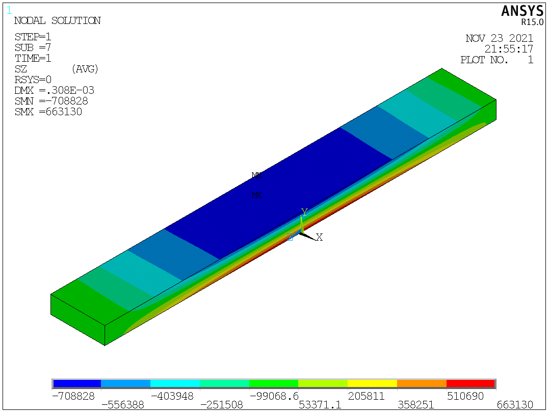
Fig. 4. Z-stress of concrete under self-weight.
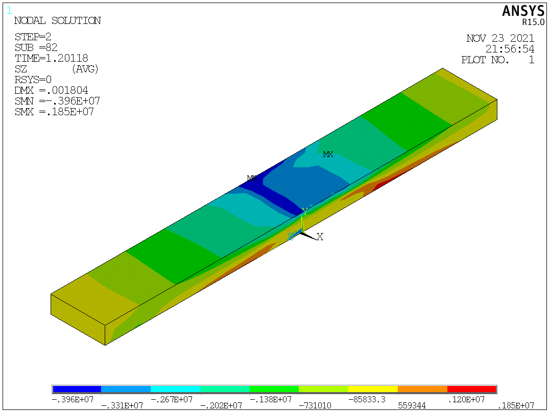
Fig. 5. Z-stress of concrete after applying the external load.
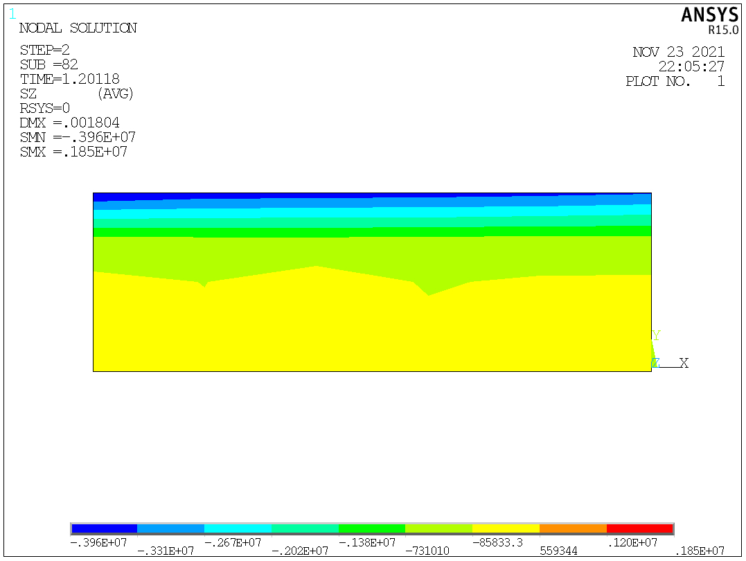
Fig. 6. The section view of z-stress of concrete after applying the external load.

Fig. 7. Z-stress of the carbon fiber sheet after applying the external load.
