This post presents an example of stationary crack analysis based on the extended FEM (XFEM). A common way to model the stress concentration at a crack tip is using KSCON command which specifies a keypoint about which an area mesh will be skewed. For stationary crack analysis, reasonable accuracy can be achieved using KSCON, although more computation resources are needed as the mesh near the crack tip should be refined. By contrast, XFEM is free of this limitation and there is no need to remesh the model.
In this example, a single-edge cracked square plate under uniform in-plane compression on two opposite edges is analyzed. J-integral and stress intensity factors K1, K2 are computed. To ensure the convergence of results, dimensionless K1 is compared with a published result. The stress results and nodal coordinates are exported at the end. The stress results can be interpolated and used in numerical integration if needed.

Fig. 1. A single-edge cracked square plate under uniform in-plane compression
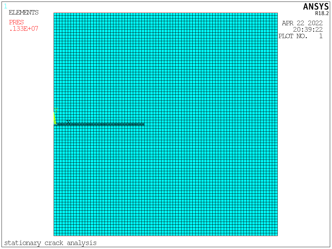
Fig. 2. Discretization
The APDL is attached (annotations are in lowercase):
FINISH
/CLEAR
/TITLE,STATIONARY CRACK ANALYSIS

/PREP7
!unit: N, m

WIDTH=0.8
HEIGHT=0.8
THICK=0.008
CRX=0.4												!crack length/width
CRKLENGTH=CRX*WIDTH									!crack length
NU=0.3												!Poisson's ratio
RO=1												!density
YMODU=73e9											!Young's modulus
BEND_RIGI=YMODU*THICK**3/(12*(1-nu**2))				!bending rigidity of the plate
PI=2*ASIN(1)
FY=-0.1*2.009*(PI**2*BEND_RIGI)/WIDTH**2/THICK		!Fy force (unit: N/m^2)
NUM_CONTOUR=8										!the number of contours

! element types
ET,1,182
KEYOPT,1,3,2
! continuum material behavior
MP,EX,1,YMODU
MP,NUXY,1,NU
MP,DENS,1,RO
! define keypoints
K,1,0,-HEIGHT/2
K,2,WIDTH,-HEIGHT/2
K,3,WIDTH,HEIGHT/2
K,4,0,HEIGHT/2
! define area with KP
A,1,2,3,4
! set up the meshing size
XNUME=79				!the number of elements in x, which should be odd
YNUME=79				!the number of elements in y, which should be odd
LSEL,S,LINE,,1,3,2
LESIZE,ALL,,,XNUME,,,,,1
LSEL,S,LINE,,2,4,2
LESIZE,ALL,,,YNUME,,,,,1
! mesh the area
TYPE,1
MAT,1
MSHKEY,1
AMESH,ALL
ALLSEL
! element component required for XFENRICH command
ESEL,S,CENT,Y,-HEIGHT/4,HEIGHT/4
ESEL,R,CENT,X,0,WIDTH
CM,TESTCMP,ELEM
ALLSEL
! define enrichment identification
XFENRICH,ENRICH1,TESTCMP,,SING,1.5
ALLSEL
!!!!!!!!!!!!!
	! initial crack data
!!!!!!!!!!!!!!!!
SELTOL,1E-8						!set the tolerance
YC=0
XC=CRKLENGTH
NSEL,S,LOC,X,0,XC
ESLN,S
ESEL,R,CENT,Y,-1E-3,1E-3
CM,CENELEM,ELEM
NELEM=1000
IEL=0
PHI=0
PSI=0
*DO,I,1,NELEM,1
	IEL=ELNEXT(IEL)				!next selected element having an element number greater than IEL.
	*IF,IEL,NE,0,THEN
		*DO,J,1,4,1
			ND=NELEM(IEL,J)		!node number in position J of element IEL.
			PHI=NY(ND)-YC
			PSI=NX(ND)-XC
			XFDATA,ENRICH1,LSM,IEL,ND,PHI,PSI
		*ENDDO
	*ENDIF
*ENDDO
XFLIST
! crack tip element
ESEL,S,CENT,X,XC-WIDTH/XNUME/2,XC+WIDTH/XNUME/2
ESEL,R,CENT,Y,-1E-4,1E-4
CM,CRKTIPELEM,ELEM
ALLSEL

! boundary condition: bottom face
NSEL,S,LOC,Y,-HEIGHT/2
SF,ALL,PRES,-FY
ALLSEL
! boundary condition: top face
NSEL,S,LOC,Y,HEIGHT/2
SF,ALL,PRES,-FY
ALLSEL

/SOLU
ANTYPE,0
TIME,1
DELTIM,0.1,1E-1,0.2
OUTRES,ALL,ALL
!CINT calculations
CINT,NEW,1
CINT,TYPE,JINT
CINT,CXFE,CRKTIPELEM
CINT,NCON,NUM_CONTOUR
CINT,NORM,0,2

CINT,NEW,2
CINT,TYPE,SIFS
CINT,CXFE,CRKTIPELEM
CINT,NCON,NUM_CONTOUR
CINT,NORM,0,2
SOLVE
FINISH

/POST1
SET,LAST,LAST
/OUT
/COM ****** RESULTS ******
/COM
/COM ****** PRINT NODAL RESULTS ******
/COM
/COM >>> JINTEGRAL
/COM
PRCINT,1,,JINT
/COM
/COM >>> MODE 1 STRESS INTENSITY FACTOR
/COM
PRCINT,2,,K1
/COM
/COM >>> MODE 2 STRESS INTENSITY FACTOR
/COM
PRCINT,2,,K2
/COM
*DIM,K1,,NUM_CONTOUR
*DO,I,1,NUM_CONTOUR
*GET,K1_CONTOUR,CINT,2,CTIP,22401,CONTOUR,I,DTYPE,K1
K1(I)=K1_CONTOUR
*ENDDO
*CREATE,K1OUTPUT,MAC
*CFOPEN,K1RESULTS,TXT
*VWRITE,K1(1)
(F13.4)
*CFCLOS
*END
K1OUTPUT

PLNSOL,S,Y
/DEVICE,VECTOR,0
/CTYPE,0
!/CVAL,1,-0.35E8,-0.25E8,-0.15E8,-0.1E8,-0.05E8,0,400000,855000
!/EXIT,nosave

ALLSEL
*GET,NUM_NODE,NODE,,COUNT
*DIM,NODE_COOR,ARRAY,NUM_NODE,2
*DIM,NODE_SX,ARRAY,NUM_NODE,1
*DIM,NODE_SY,ARRAY,NUM_NODE,1
*DIM,NODE_SXY,ARRAY,NUM_NODE,1
*DO,I,1,NUM_NODE
NODE_COOR(I,1)=NX(I)
NODE_COOR(I,2)=NY(I)
*GET,N_SX,NODE,I,S,X
*GET,N_SY,NODE,I,S,Y
*GET,N_SXY,NODE,I,S,XY
NODE_SX(I)=N_SX
NODE_SY(I)=N_SY
NODE_SXY(I)=N_SXY
*ENDDO

*CREATE,NODALRESULTS,MAC
*CFOPEN,X_COOR,TXT
*VWRITE,NODE_COOR(1,1)
(F10.8)
*CFCLOS
*CFOPEN,Y_COOR,TXT
*VWRITE,NODE_COOR(1,2)
(F10.8)
*CFCLOS
*CFOPEN,SIGMA_X,TXT
*VWRITE,NODE_SX(1)
(F13.4)
*CFCLOS
*CFOPEN,SIGMA_Y,TXT
*VWRITE,NODE_SY(1)
(F13.4)
*CFCLOS
*CFOPEN,SIGMA_XY,TXT
*VWRITE,NODE_SXY(1)
(F13.4)
*CFCLOS
*END
NODALRESULTS
Fig. 3. J-integral and stress intensity factors
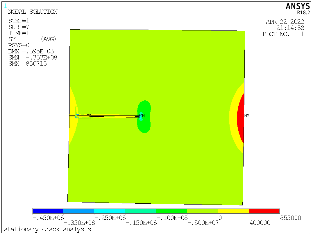
Fig. 4. The stress in Y-direction

Pingback: Stationary Crack Analysis: J-integral and Stress Intensity Factor Calculation | Xutao Sun