We talked about 2D stationary crack analysis using KSCON in the last post. This time let’s have a look at the 3D model using solid elements. A long plate with a centre crack is subjected to an end tensile stress. The sketch of the problem is as follows.
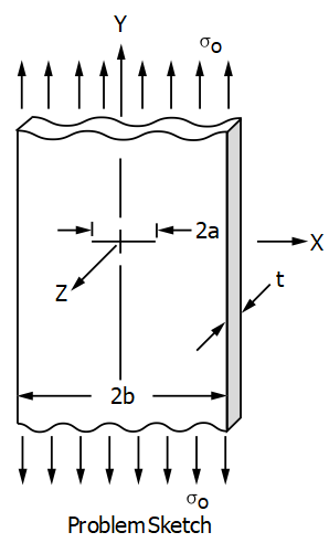
A one-quarter model is used because of symmetry. The plane strain condition is achieved by constraining UZ degrees of freedom of all the nodes (displacements in the Z-direction). A representative FE model is shown in the following figure.
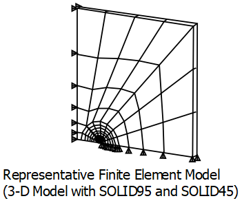
The code of this post is excerpted from VM143_ANSYS Mechanical APDL Verification Manual. A macro named FRACT is used to create the SOLID95 crack tip elements from the SOLID45 model using a weighted midside node position (quarter-point location). The macro is well written and can be applied to different scenarios without much editing. Instead of using CINT command, the stress intensity factor is calculated using KCALC command. KCALC is based on the displacement extrapolation method. J-Integral is calculated through path operations and is compiled in the other macro named JIN1.
The APDL is attached as follows (annotations are in lowercase).
/COM,ANSYS MEDIA REL. 182 (07/10/2017) REF. VERIF. MANUAL: REL. 182
/VERIFY,VM143


*CREATE,FRACT,MAC
!  macro to create 3D SOLID95 crack tip elements from 3D SOLID45 elements
!     make a component containing the crack tip nodes (CRACKTIP)
!     the crack tip is between nodes K and O
!     set element type to point to SOLID95
!     set ARG1 to  N  (the type of the elements around the crack tip)
!
/NOPR
NSEL,ALL
*GET,N,NODE,,NUM,MAX                 ! current maximum node number
CMSEL,S,CRACKTIP                     ! select the tip nodes
ESLN                                 ! any elements attached
*GET,ELMAX,ELEM,,NUM,MAX             ! current maximum element number
*DO,IEL,1,ELMAX                      ! loop on max element
   ELMI=IEL
   *IF,ELMI,LE,0,EXIT                ! no more selected
   *GET,ELTYPE,ELEM,ELMI,ATTR,TYPE   ! get element type
   *IF,ELTYPE,NE,ARG1,CYCLE          ! check for selected element
   N3 = NELEM(ELMI,3)                ! get node 3 (K)
   *IF,NSEL(N3),LE,0,CYCLE           ! it must be selected
   N7 = NELEM(ELMI,7)                ! get node 7 (L)
   *IF,NSEL(N7),LE,0,CYCLE           ! it must also be selected
   N1 = NELEM(ELMI,1)                ! get node 1 (I)
   N2 = NELEM(ELMI,2)                ! get node 2 (J)
   N5 = NELEM(ELMI,5)                ! get node 5 (M)
   N6 = NELEM(ELMI,6)                ! get node 6 (N)

   X3 = 0.75*NX(N3)                  ! weighted position of N3
   Y3 = 0.75*NY(N3)
   Z3 = 0.75*NZ(N3)
   X  = 0.25*NX(N2) + X3             ! quarter point location ( node (R) )
   Y  = 0.25*NY(N2) + Y3
   Z  = 0.25*NZ(N2) + Z3
   N  = N + 1                        ! next node
   N10 = N
   N,N10,X,Y,Z                       ! midside node location
   X  = 0.25*NX(N1) + X3
   Y  = 0.25*NY(N1) + Y3
   Z  = 0.25*NZ(N1) + Z3
   N  = N + 1
   N12= N
   N,N12,X,Y,Z
   X7 = 0.75*NX(N7)
   Y7 = 0.75*NY(N7)
   Z7 = 0.75*NZ(N7)
   X  = 0.25*NX(N6) + X7
   Y  = 0.25*NY(N6) + Y7
   Z  = 0.25*NZ(N6) + Z7
   N  = N + 1
   N14 = N
   N,N14,X,Y,Z
   X  = 0.25*NX(N5) + X7
   Y  = 0.25*NY(N5) + Y7
   Z  = 0.25*NZ(N5) + Z7
   N  = N + 1
   N16 = N
   N,N16,X,Y,Z
   N4=N3
   N8=N7
   NSEL,ALL
   TYPE,3
   EN,ELMI,N1,N2,N3,N4,N5,N6,N7,N8   ! redefine the element
   EMORE,0,N10,0,N12,0,N14,0,N16
   EMORE,
*ENDDO
CMSEL,U,CRACKTIP                     ! unselect the tip nodes
NUMMRG,NODE                          ! merge midside nodes
NSEL,ALL                             ! select all elements
ESEL,ALL                             ! select all elements
/GOPR
*END

!***************************************************************


/PREP7
SMRT,OFF
/TITLE, VM143, FRACTURE MECHANICS STRESS INTENSITY  - CRACK IN A FINITE WIDTH PLATE
C***    BROWN AND SRAWLEY, ASTM SPECIAL TECHNICAL PUBLICATION NO. 410.
/COM,     ****** CRACK IN 3-DIMENSIONS USING SOLID45 AND SOLID95
ANTYPE,STATIC                ! static analysis
ET,1,SOLID45
ET,2,SOLID45                 ! elements around the crack tip
ET,3,SOLID95                 ! crack tip elements created using macro fract
MP,EX,1,3E7
MP,NUXY,1,.3
CSYS,1                       ! cylindrical coordinate system
N,1
NGEN,9,20,1
N,11,.8
N,171,.8,180
FILL,11,171,7,31,20
CSYS,0                       ! cartesian coordinate system
FILL,1,11,9,2,1,9,20,3
N,15,4
N,75,4,5
FILL,15,75,2,35,20
N,155,-1,5
FILL,75,155,3,95,20
N,172,-1
FILL,155,172,5,177,-1,,,.15
FILL,11,15,3,,,7,20,3
NGEN,2,200,1,177,,,,.25
E,2,22,1,1,202,222,201,201
EGEN,8,20,-1
E,2,3,23,22,202,203,223,222
EGEN,8,20,-1
EGEN,9,1,-8
EGEN,5,1,73,78
E,171,151,173,172,371,351,373,372
E,151,131,174,173,351,331,374,373
E,131,132,175,174,331,332,375,374
EGEN,3,1,-1
E,134,135,155,177,334,335,355,377
TYPE,2
EMODIF,1                    ! modify elements 1 to 8 from type,1 to type,2
*REPEAT,8,1
NUMMRG,NODE                 ! merge coincident nodes
NSEL,S,LOC,X,0
NSEL,R,LOC,Y,0
CM,CRACKTIP,NODE
/NERR,0                     ! temporarily no warnings or errors printout
                            ! (in order to avoid warning messages due to
                            !  midside nodes location)
FRACT,2                     ! conversion macro, type 2 is SOLID45
                            ! elements around the crack tip
/NERR,DEFA                  ! turn on the warnings or errors printout
/OUTPUT
OUTPR,,ALL
OUTPR,VENG,ALL              ! store strain energy for J-integral evaluation
NSEL,S,LOC,X,-1
DSYM,SYMM,X                 ! symmetric B.C.'s at X = -1
NSEL,S,LOC,X,0,4
NSEL,R,LOC,Y,0
DSYM,SYMM,Y                 ! symmetric B.C.'s at Y = 0 except crack nodes
NSEL,ALL
D,ALL,UZ                    ! Z constraints for plane strain problem
NSEL,S,LOC,Y,5
SF,ALL,PRES,-.5641895
NSEL,ALL
ESEL,ALL
FINISH
/OUTPUT,SCRATCH
/SOLU
SOLVE
FINISH
/OUTPUT
/POST1
ETABLE,SENE,SENE             ! retrieve strain energy per element
ETABLE,VOLU,VOLU             ! retrieve volume per element
C*** IN POST1 DETERMINE KI (STRESS INTENSITY FACTOR) USING KCALC !**
PATH,KI1,3,,48                ! define path with name = "KI1"
PPATH,1,1                    ! define path points by node
PPATH,2,406
PPATH,3,162
KCALC,,,1                    ! compute KI for a half-model with symm. B.C.
*GET,KI1,KCALC,,K,1          ! get KI as parameter KI1


!********************************************************************************
!**************************  J-integral user file  *****************************
!*******************************************************************************
! ****note:- in general usage, the user file would be available in the
!            local directory rather than being created in the input
!*******************************************************************************
*CREATE,JIN1
STINFC                        ! data block name
SEXP,W,SENE,VOLU,1,-1         ! calculate strain energy density
PATH,JINT,4,50,48             ! define path with name = "JINT"
PPATH,1,ARG1                  ! define path points by node
PPATH,2,ARG2
PPATH,3,ARG3
PPATH,4,ARG4
PDEF,W,ETAB,W                 ! put strain energy density on the path
PCALC,INTG,J,W,YG             ! integrate energy w.r.t. global Y
*GET,JA,PATH,,LAST,J          ! get final value of integral for 1st term of J
PDEF,CLEAR                    ! clear old path variables
PVECT,NORM,NX,NY,NZ           ! define the path unit normal vector
PDEF,INTR,SX,SX               ! put stress SX on the path
PDEF,INTR,SY,SY               ! put stress SY on the path
PDEF,INTR,SXY,SXY             ! put stress SXY on the path
PCALC,MULT,TX,SX,NX           ! calculate traction TX
PCALC,MULT,C1,SXY,NY          !   TX = SX*NX + SXY*NY
PCALC,ADD,TX,TX,C1
PCALC,MULT,TY,SXY,NX          ! calculate traction TY
PCALC,MULT,C1,SY,NY           !   TY = SXY*NX + SY*NY
PCALC,ADD,TY,TY,C1
*GET,DX,PATH,,LAST,S          ! define path shift as 1% of path length
DX=DX/100
PCALC,ADD,XG,XG,,,,-DX/2      ! shift path from X to X-DX/2 (global X dir.)
PDEF,INTR,UX1,UX              ! define UX at X-DX
PDEF,INTR,UY1,UY              ! define UY at X-DX
PCALC,ADD,XG,XG,,,,DX         ! shift path from X-DX/2 to X+DX/2
PDEF,INTR,UX2,UX              ! define UX at X+DX
PDEF,INTR,UY2,UY              ! define UY at X+DX
PCALC,ADD,XG,XG,,,,-DX/2      ! shift path back to original position
C=(1/DX)
PCALC,ADD,C1,UX2,UX1,C,-C     ! calculate derivative DUX/DX
PCALC,ADD,C2,UY2,UY1,C,-C     ! calculate derivative DUY/DX
PCALC,MULT,C1,TX,C1           ! define integrand
PCALC,MULT,C2,TY,C2           !   = TX*DUX/DX + TY*DUY/DX
PCALC,ADD,C1,C1,C2
PCALC,INTG,J,C1,S             ! form second integral (w.r.t. path length S)
*GET,JB,PATH,,LAST,J          ! get final value of integral for 2nd term of J
JINT=2*(JA-JB)                ! add both terms and double for half models
PDEF,CLEAR                    ! clear path variables
*END
!*****************************************************************


C**************** IN POST1 DETERMINE KI FROM J-INTEGRAL !***********************
CON1=30E6/(1-(0.3*0.3))       ! J-to-KI conversion factor
*ULIB,JIN1                    ! assign local file JIN1 as user file
*USE,STINFC,4,45,125,164      ! use data block stinfc and give path nodes
KI2=SQRT(CON1*JINT)           ! calculate KI from J
*STATUS,KI1                   ! view results
*STATUS,KI2
*DIM,LABEL,CHAR,2,2
*DIM,VALUE,,2,3
LABEL(1,1) = 'BY DISP ','BY J-'
LABEL(1,2) = 'EXTRP ','INT'
*VFILL,VALUE(1,1),DATA,1.0249,1.0249
*VFILL,VALUE(1,2),DATA,KI1,KI2
*VFILL,VALUE(1,3),DATA,ABS(KI1/1.0249),ABS(KI2/1.0249)
SAVE,TABLE_1
FINISH

