In this post, we are going to explore the mapped meshing for 2D models. Five examples are provided. Some important commands in 2D meshing such as LESIZE, AMAP, LCOMB, etc., will be demonstrated. To perform mapped meshing, sometimes it is necessary to divide the area into a set of subdomains. Thus those commands for area subtraction such as ASBW, ASBA, ASBL, etc. are useful. For areas featuring a repetitive pattern, the commands for generating areas like AGEN and ARSYM will be used.
1. An orifice plate
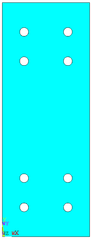
After creating the geometry, the area is divided into a number of small regions. Some (but not necessarily all) of these regions consist of 4 edges. In this example, the regions containing a curve have 5 edges. To apply mapped meshing in those regions, AMAP is used.
FINISH
/CLEAR
/PREP7
A0=300
B0=800
R0=15
BLC4,,,A0,B0
CYL4,A0/4,B0/8,R0
AGEN,2,2,,,A0/2
AGEN,2,2,3,1,,B0/8
AGEN,2,2,5,1,,B0*5/8
ASEL,S,,,2,9,1
CM,A2CM,AREA
ALLSEL
ASBA,1,A2CM
!cut the geometry
WPROTA,,-90
*DO,I,1,5
	WPOFFS,,,B0/16
	ASBW,ALL
*ENDDO
WPOFFS,,,B0*5/16
*DO,I,1,5
	WPOFFS,,,B0/16
	ASBW,ALL
*ENDDO
WPROTA,,,90
*DO,I,1,3
	WPOFFS,,,A0/4
	ASBW,ALL
*ENDDO
WPCSYS,-1
NUMCMP,ALL
!meshing
LSEL,S,RADIUS,,R0
LESIZE,ALL,,,8
LSEL,INVE
LESIZE,ALL,,,4
LSEL,ALL
ET,1,82
MSHAPE,0,2D
MSHKEY,1
ASEL,U,LOC,Y,B0/16,B0*5/16
ASEL,U,LOC,Y,B0*11/16,B0*15/16
LSLA,S
LSEL,R,TAN1,X			!select vertical lines
LESIZE,ALL,50,,,,1
AMESH,ALL
ALLSEL
AMAP,21,30,31,54,62
AMAP,22,31,32,54,64
AMAP,32,29,30,62,76
AMAP,33,29,32,64,76
AMAP,42,34,35,76,82
AMAP,43,35,36,76,84
AMAP,41,33,34,53,82
AMAP,44,33,36,53,84
AMAP,19,22,23,49,64
AMAP,20,23,24,49,60
AMAP,9,21,22,64,74
AMAP,31,21,24,60,74
AMAP,38,26,27,74,84
AMAP,39,27,28,74,80
AMAP,37,25,26,50,84
AMAP,40,25,28,50,80
AMAP,17,14,15,43,59
AMAP,18,15,16,43,63
AMAP,7,13,14,59,73
AMAP,8,13,16,63,73
AMAP,34,18,19,73,79
AMAP,30,17,18,79,44
AMAP,35,19,20,73,83
AMAP,36,17,20,44,83
AMAP,15,6,7,39,63
AMAP,16,7,8,39,58
AMAP,4,6,5,63,71
AMAP,5,5,8,58,71
AMAP,27,10,11,71,83
AMAP,28,11,12,71,78
AMAP,26,9,10,83,40
AMAP,29,9,12,40,78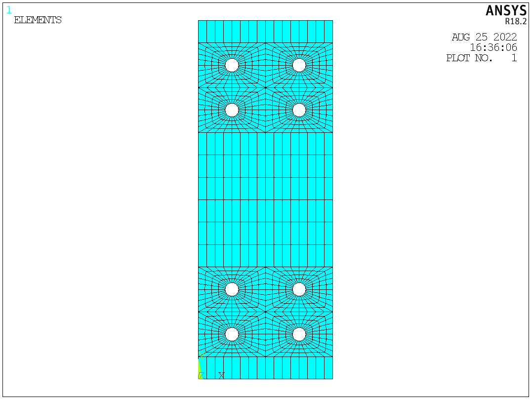
2. A corner bracket
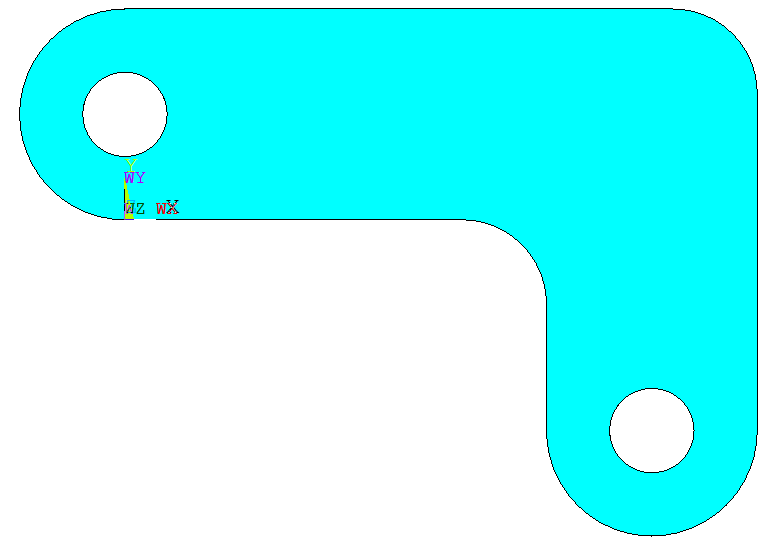
This example is similar to the first one. The area is divided, and then AMAP is applied to those non-quadrilateral regions.
FINISH
/CLEAR
/PREP7
BLC4,,,150,50
BLC4,100,,50,-50
CYL4,,25,25
CYL4,125,-50,25
AADD,ALL
NUMCMP,ALL
CYL4,,25,10
CYL4,125,-50,10
ASEL,S,,,2,3
CM,A1CM,AREA
ASEL,ALL
ASBA,1,A1CM
LCOMB,1,6
LFILLT,1,2,20
ASBL,4,6
ADELE,1,,,1
LFILLT,3,4,20
AL,18,19,20
AADD,ALL
NUMCMP,ALL
!cut the geometry
WPROTA,,90
WPOFFS,,,-25
ASBW,ALL
WPOFFS,,,75
ASBW,ALL
WPROTA,,,90
ASBW,ALL
WPOFFS,,,125
ASBW,ALL
WPCSYS,-1
WPOFFS,25
WPROTA,,,90
ASBW,ALL
KWPAVE,18
ASBW,ALL
KWPAVE,3
WPROTA,,90
ASBW,ALL
KWPAVE,21
WPROTA,,-45
ASBW,8
WPCSYS,-1
!meshing
ET,1,PLANE82
MSHAPE,0,2D
MSHKEY,1
ESIZE,6
LESIZE,33,,,6
LESIZE,37,,,6
LESIZE,42,,,6
AMESH,3,5,2
AMAP,6,9,10,4,23
AMAP,7,9,12,1,23
AMESH,11,13,2
AMESH,1,9,8
AMESH,2,4,2
AMAP,16,3,18,26,28
AMAP,12,14,15,5,28
AMAP,15,13,14,6,28
LCOMB,19,22
LCOMB,27,46
AMESH,10,14,4
3. A plate with a hole
In this example, to balance the accuracy and computational effort, dense elements are generated near the hole, while the element size increases when the element is far away from the hole. This is achieved by specifying the spacing ratio in LESIZE.
FINISH
/CLEAR
/PREP7
A0=100
BLC4,,,A0,A0
CYL4,,,A0/100
ASBA,1,2
CSYS,1
K,50,A0/20
K,51,A0/20,90
L,50,51
ASBL,ALL,1
!meshing
ET,1,82
MSHAPE,0,2D
MSHKEY,1
LESIZE,5,,,8
LESIZE,1,,,10
LESIZE,4,,,8,5
LESIZE,6,,,8,5
AMESH,1
LESIZE,7,,,20,0.1
LESIZE,8,,,20,0.1
AMAP,2,50,51,2,4
CSYS,0
!using symmetry
ARSYM,X,ALL
ARSYM,Y,ALL
NUMMRG,ALL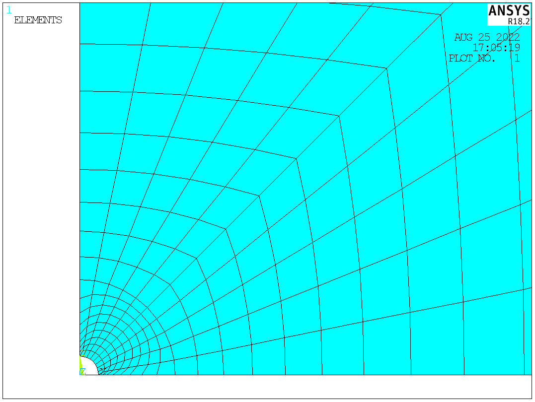
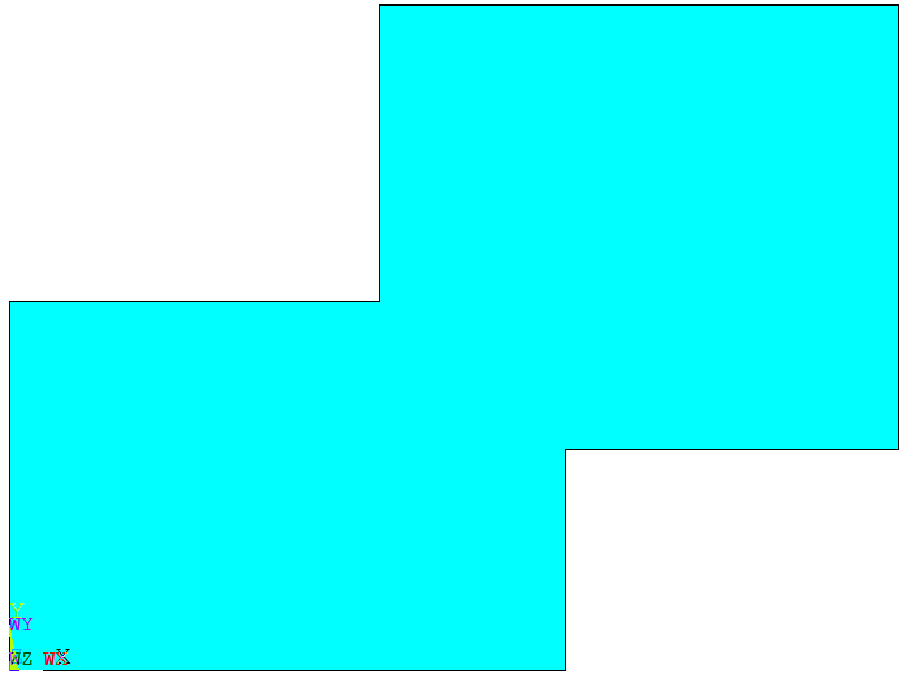
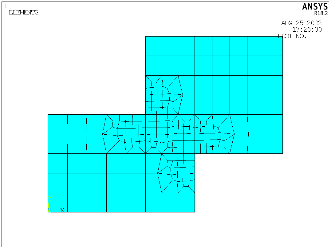
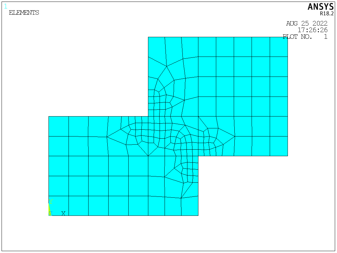
4. A z-shaped area
In this example, the mesh of the connection region is refined using KREFINE.
FINISH
/CLEAR
/PREP7
BLC4,,,15,10
BLC4,10,6,14,12
AADD,ALL
WPROTA,,-90
WPOFFS,,,6
ASBW,ALL
WPOFFS,,,4
ASBW,ALL
WPROTA,,,90
WPOFFS,,,10
ASBW,ALL
WPOFFS,,,5
ASBW,ALL
WPCSYS,-1
!meshing
ET,1,82
ESIZE,2
MSHAPE,0,2D
MSHKEY,1
AMESH,ALL
KREFINE,9,10,1,1,,OFF		!no postprocessing will be done
ACLEAR,ALL
AMESH,ALL
KREFINE,9,10,1,1,,SMOOTH	!Smoothing will be done. Node locations may change
ACLEAR,ALL
AMESH,ALL
KREFINE,9,10,1,1,,CLEAN			!Smoothing and cleanup will be done. Existing elements may be deleted, and node locations may change (default)
OFF
SMOOTH
CLEAN
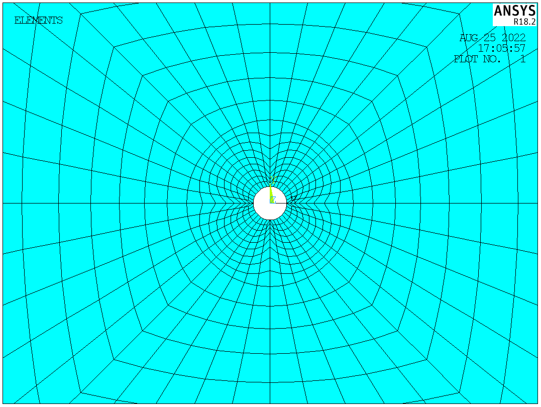
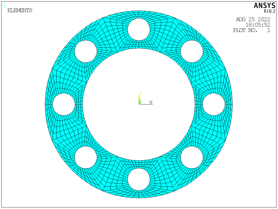
5. An annular plate with distributed holes
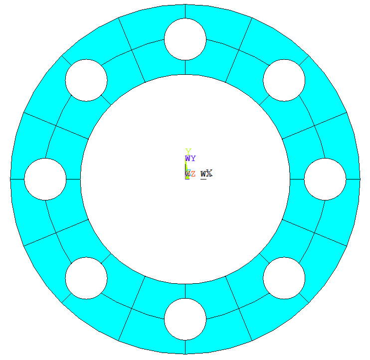
In this example, 8 holes distribute evenly in the annular plate. As the plate shows a periodic pattern, a small area is created and meshed. Then the area is copied 8 times to generate the whole plate.
FINISH
/CLEAR
/PREP7
R1=15
R2=25
R3=3
N=8
CYL4,,,R1,,R2,180/N
CYL4,0.5*(R1+R2),,R3
ASBA,1,2
KL,2
LARC,6,8,4,0.5*(R1+R2)
ASBL,ALL,4
LESIZE,4,,,4
LESIZE,10,,,4
LESIZE,6,,,10
LESIZE,3,,,6
LESIZE,8,,,4
LESIZE,5,,,10
LESIZE,9,,,4
LESIZE,1,,,6
LESIZE,7,,,4
ET,1,82
MSHAPE,0,2D
AMAP,2,6,7,4,8
AMAP,1,5,6,8,1
!LREFINE,5,6,1,1,SMOOTH
ARSYM,Y,ALL
CSYS,1
AGEN,N,ALL,,,,360/N
NUMMRG,ALL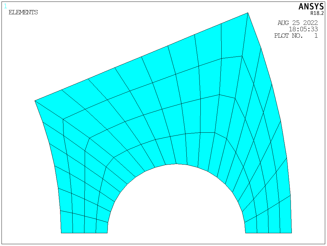

Pingback: The application of contact elements: A bolted beam-column connection | Xutao Sun
Pingback: Examples of 3D Mapped Meshing | Xutao Sun