In this post, I will show an example of using MACRO and *DOWHILE. The APDL is developed to model an experiment as shown below. Essentially it is a clamped-clamped cracked beam carrying a body. An important feature of the body is that its mass distributes far away from its centroid, hence the rotary inertia would not be negligible. The body can be located in a sequence of positions. During the experiment, the body is fixed on the cracked beam at a specific location, and the natural frequencies of the cracked beam carrying the body are measured through the impact hammer test. Then the body is moved to the next location and the measurement is repeated. It is expected that there is a frequency shift when the mass passes the crack.
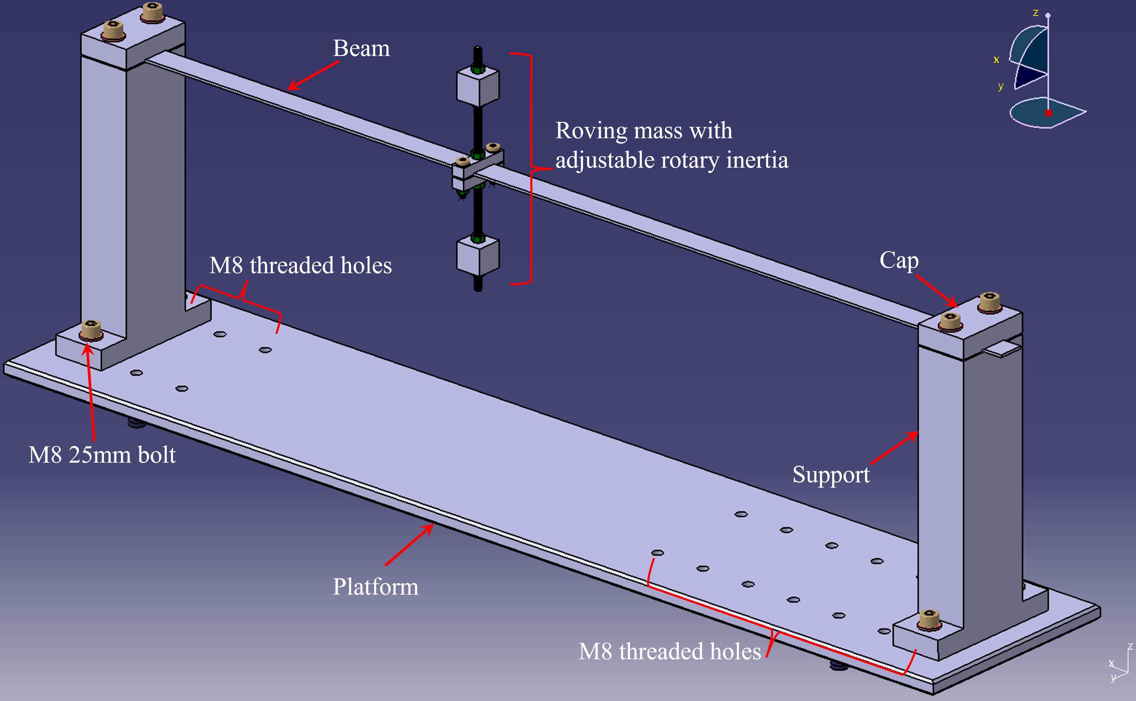
Figure 1. The experiment design in CATIA V5.
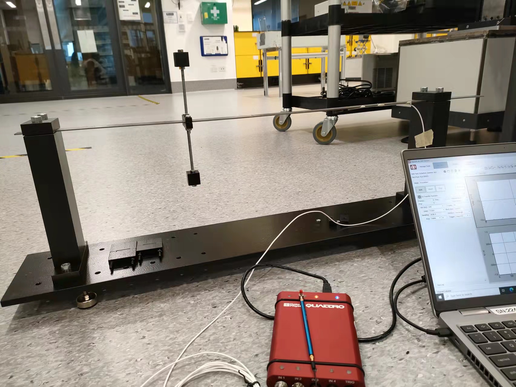
Figure 2. The experiment set-up.
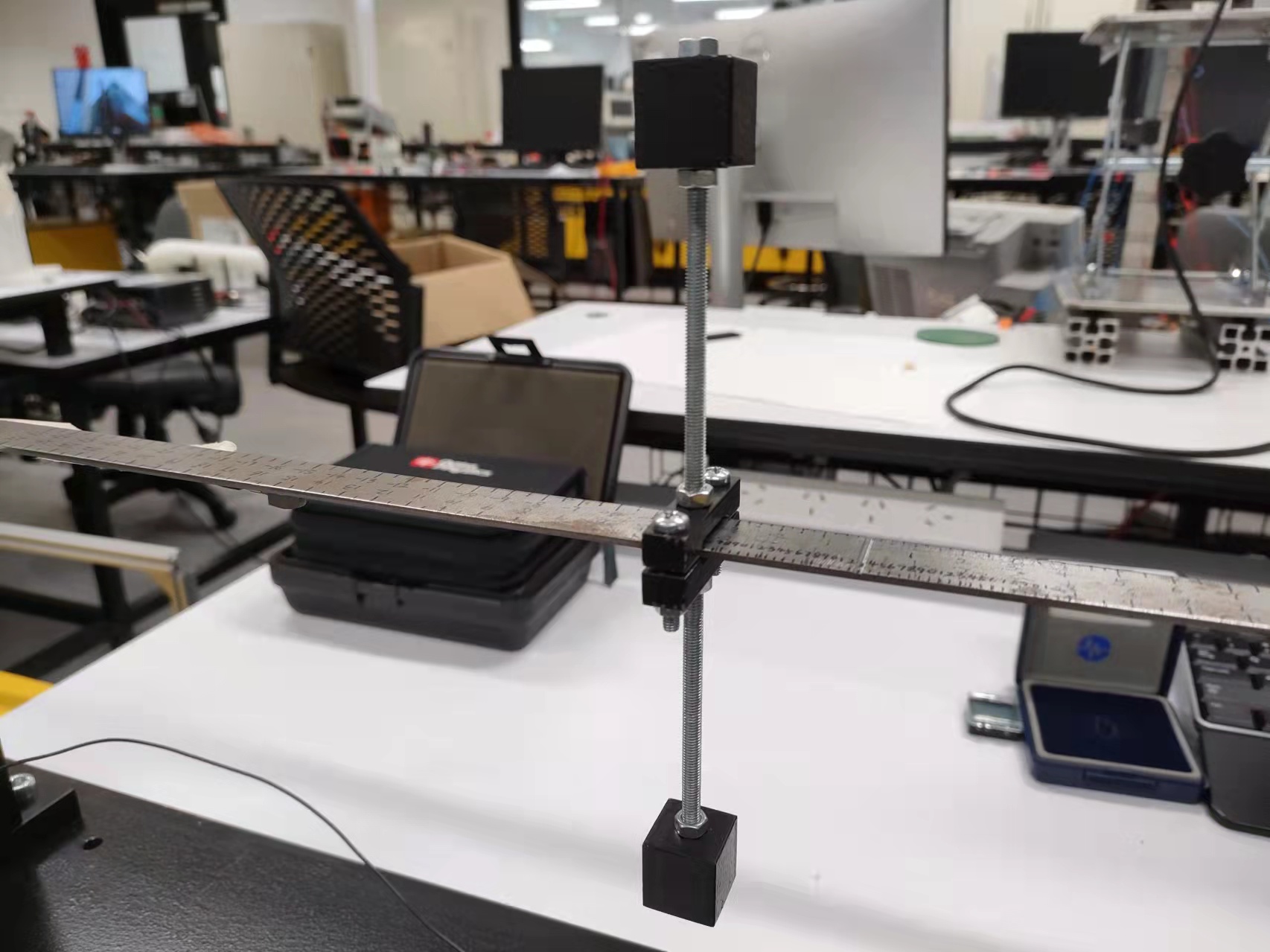
Figure 3. A series of marks on the cracked beam showing the roving body locations.
The APDL is to perform the modal analysis when the body roves on the cracked beam. If we examine the problem introduced above, we would notice the repetitive pattern in this problem. It’s the same cracked beam and it’s the same roving body. Only the location of the body is varying. The good thing is those locations are discrete but consecutive (same distance between two adjacent locations). Considering this feature, the APDL is compiled in such a way that the roving body and the cracked beam are generated as a whole body (so the rigid connection between the body and beam is not a concern), and the process of creating the model is packaged in a MACRO.
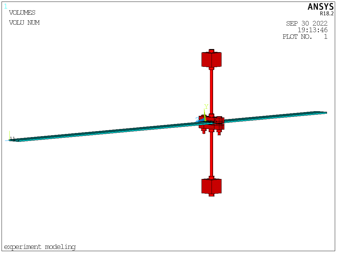
Figure 4. The volume plot.
With the above MACRO, the model can be solved whenever the body location changes. By defining a parameter controlling the body location (hence controlling the geometry of the model), a *DOWHILE loop can be developed by indexing the controlling parameter. Within the loop, whenever the controlling parameter changes, the MACRO is performed and the model is solved. Then all parameters (including the results) are saved using PARSAV. Then clear the database using /CLEAR, read the parameters again using PARRES, change the controlling parameter, run the MACRO, and solve the new model. This process is repeated until the condition of *DOWHILE is reached.
The APDL is attached here (annotations are in lowercase):
FINISH
/CLEAR
/TITLE,EXPERIMENT MODELLING

*CREATE,F_CALCULATION,MAC
	/PREP7
	! ET,1,SOLID186
	ET,1,SOLID92
	MP,EX,1,188.58219E9						!beam material, CR1: 190.69637
	MP,PRXY,1,0.303
	MP,DENS,1,7571.43
	MP,EX,2,190E9						!mass material
	MP,PRXY,2,0.265
	MP,DENS,2,7225.00

	!geometry of the roving mass
	BLC4,,,0.041,0.008,0.01				!part A
	BLC4,,-0.001,0.041,-0.008,0.01		!part B
	/VIEW,1,1,1,1
	/ANG,1
	/REP,FAST
	WPOFFS,0.01
	WPROTA,,,90
	VSBW,ALL
	WPOFFS,,,0.021
	VSBW,ALL
	WPOFFS,,0.001
	WPROTA,,90
	VSBW,ALL
	VSEL,S,LOC,X,0.01,0.031
	VSEL,R,LOC,Y,0,0.001
	VDELE,ALL,,,1
	ALLSEL
	! /TRLCY,VOLU,0.8,ALL,,,
	! /REPLOT
	! /PNUM,VOLU,1
	! /VIEW,1,,,1
	! /ANG,1
	! /REP,FAST
	WPOFFS,,,0.004
	VSBW,ALL
	WPOFFS,,,-0.006
	VSBW,ALL
	WPROTA,,,-90
	WPOFFS,,,0.004
	VSBW,ALL
	WPOFFS,,,0.002
	VSBW,ALL
	VSEL,S,LOC,X,0.01,0.031
	VSEL,R,LOC,Y,-0.003,0.003
	VSEL,R,LOC,Z,0,0.004
	VDELE,ALL,,,1
	ALLSEL
	VSEL,S,LOC,X,0.01,0.031
	VSEL,R,LOC,Y,-0.003,0.003
	VSEL,R,LOC,Z,0.006,0.01
	VDELE,ALL,,,1
	ALLSEL
	VSEL,S,LOC,Y,0,0.008
	VADD,ALL
	CM,PARTA,VOLU
	ALLSEL
	VSEL,S,LOC,Y,-0.009,0
	VADD,ALL
	! CM,PARTB,VOLU
	ALLSEL
	WPCSYS,-1
	WPOFFS,,0.001
	WPROTA,,-90
	CYL4,0.0205,-0.005,0.0024,,,,0.002
	/VIEW,1,1,1,1
	/ANG,1,-30,XS,1
	/REP,FAST
	VSBV,PARTA,1,,,DELETE
	WPCSYS,-1

	!M4 bolts and nuts
	WPOFFS,0.005,,0.005
	WPROTA,,90
	CYL4,,,RAD_M4BOLT,,,,0.001
	WPOFFS,,,-0.008
	CYL4,,,RAD_M4BOLT_HAT,,,,-THICK_M4BOLT_HAT
	WPOFFS,,,0.017
	CYL4,,,RAD_M4BOLT,,,,EXPOS_M4BOLT			!the exposed length of the M4 bolt
	CYL4,,,RAD_M4NUT,,,,THICK_M4NUT				!the approximate size of M4 nut
	WPOFFS,0.031
	CYL4,,,RAD_M4BOLT,,,,EXPOS_M4BOLT			!the exposed length of the M4 bolt
	CYL4,,,RAD_M4NUT,,,,THICK_M4NUT				!the approximate size of M4 nut
	WPOFFS,,,-0.009
	CYL4,,,RAD_M4BOLT,,,,0.001
	WPOFFS,,,-0.008
	CYL4,,,RAD_M4BOLT_HAT,,,,-THICK_M4BOLT_HAT

	!M5 rods and nuts
	!up
	WPCSYS,-1
	WPOFFS,0.0205,0.008,0.005
	WPROTA,,-90
	CYL4,,,RAD_M5ROD,,,,EXPOS_M5ROD				!M5 rod
	CYL4,,,RAD_M5NUT,,,,THICK_M5NUT				!M5 nut
	WPOFFS,,,EXPOS_M5ROD
	CYL4,,,RAD_M5NUT,,,,-THICK_M5NUT			!M5 nut
	WPOFFS,,,-THICK_M5NUT-0.02
	CYL4,,,RAD_M5NUT,,,,-THICK_M5NUT			!M5 nut
	BLC5,,,0.02,0.02,0.02						!mass A
	WPCSYS,-1
	WPOFFS,0.0205,-0.009,0.005
	WPROTA,,90
	!down
	CYL4,,,RAD_M5ROD,,,,EXPOS_M5ROD				!M5 rod
	CYL4,,,RAD_M5NUT,,,,THICK_M5NUT				!M5 nut
	WPOFFS,,,EXPOS_M5ROD
	CYL4,,,RAD_M5NUT,,,,-THICK_M5NUT			!M5 nut
	WPOFFS,,,-THICK_M5NUT-0.02
	CYL4,,,RAD_M5NUT,,,,-THICK_M5NUT			!M5 nut
	BLC5,,,0.02,0.02,0.02						!mass B
	WPCSYS,-1

	ALLSEL
	VADD,ALL
	! CM,MASS,VOLU

	!geometry of the cracked beam
	LOCAL,11,0,0.0105,-0.001,CR_LOCATION-SAMPLING/2*STEP+J*STEP+0.004		!define a local coordinate system for the beam
	CSYS,11
	WPCSYS,-1,11
	BLC4,,,0.02,0.002,-BEAM_LENGTH
	VSEL,S,LOC,Y,0.002/2
	VSEL,R,LOC,X,0.02/2
	VSEL,R,LOC,Z,-BEAM_LENGTH/2
	WPOFFS,,,-CR_LOCATION
	VSBW,ALL
	WPOFFS,,,-CR_WIDTH
	VSBW,ALL
	WPROTA,,-90
	WPOFFS,,,0.002-CR_DEPTH*0.002
	VSEL,R,LOC,Z,-CR_LOCATION-CR_WIDTH,-CR_LOCATION
	VSBW,ALL
	VSEL,R,LOC,Y,0.002-CR_DEPTH*0.002,0.002
	VDELE,ALL,,,1
	!group the beam parts
	VSEL,S,LOC,Y,0.002/2
	VSEL,R,LOC,X,0.02/2
	VSEL,R,LOC,Z,-CR_LOCATION/2
	CM,BEAM_PART_L,VOLU
	VSEL,S,LOC,Y,(0.002-CR_DEPTH*0.002)/2
	VSEL,R,LOC,X,0.02/2
	VSEL,R,LOC,Z,-CR_LOCATION-CR_WIDTH/2
	CM,BEAM_PART_M,VOLU
	VSEL,S,LOC,Y,0.002/2
	VSEL,R,LOC,X,0.02/2
	VSEL,R,LOC,Z,-CR_LOCATION-CR_WIDTH-(BEAM_LENGTH-CR_LOCATION-CR_WIDTH)/2
	CM,BEAM_PART_R,VOLU
	VSEL,A,,,BEAM_PART_M
	VSEL,A,,,BEAM_PART_L
	VADD,ALL
	! CM,CRACKEDBEAM,VOLU
	ALLSEL
	VGLUE,ALL
	/TRLCY,VOLU,0.8,ALL,,,
	/PNUM,VOLU,1
	/REP,FAST

	!mesh
	VATT,1,,1
	MSHAPE,1,3D
	SMRTSIZE,6
	MSHKEY,0
	VMESH,ALL

	LOCATION(J)=-(KZ(3)+KZ(7))/2

	!modify the material of the mass
	*GET,MASS_VOLUNUM,VOLU,0,NUM,MAX
	VSEL,S,,,MASS_VOLUNUM
	ESLV,S
	EMODIF,ALL,MAT,2
	ALLSEL

	!beam boundary conditions
	NSEL,S,LOC,Z,0
	D,ALL,ALL
	NSEL,S,LOC,Z,-BEAM_LENGTH
	D,ALL,ALL
	ALLSEL

	!solve
	/SOLU
	ANTYPE,MODAL
	MODOPT,LANB,20
	MXPAND,ALL
	! ACEL,,9.8
	SOLVE
	FINISH
	/POST1
	! SET,LIST
	*DO,I,1,20
		*GET,FREQUENCY,MODE,I,FREQ
		FREQUENCYRESULTS(I,J)=FREQUENCY
	*ENDDO
	FINISH
*END
!!!!!!!!!!!!!!!!!!!!
!start the analysis from here
!!!!!!!!!!!!!!!!!!!!
*SET,STEP,0.004
*SET,SAMPLING,20					!the number of sampling points
*SET,CR_LOCATION,0.393				!the coordinate of the left edge of the crack, CR1 beam: 0.351
*SET,CR_DEPTH,0.2
*SET,CR_WIDTH,0.002
*SET,BEAM_LENGTH,0.623

*SET,EXPOS_M4BOLT,0.008
*SET,RAD_M4BOLT,0.0019
*SET,RAD_M4NUT,0.00385
*SET,THICK_M4NUT,0.0036
*SET,RAD_M4BOLT_HAT,0.00385
*SET,THICK_M4BOLT_HAT,0.00155

*SET,EXPOS_M5ROD,0.097
*SET,RAD_M5ROD,0.0024
*SET,RAD_M5NUT,0.0039
*SET,THICK_M5NUT,0.0044

*DIM,FREQUENCYRESULTS,ARRAY,20,SAMPLING
*DIM,LOCATION,ARRAY,SAMPLING		!storing mass locations

*SET,J,1							!the initial index of the sampling position
*SET,WHILE_PAR,SAMPLING+1-J			!the par for *dowhile loop
*DOWHILE,WHILE_PAR
	/NERR,0,,,,0
	/UIS,MSGPOP,3
	F_CALCULATION
	PARSAV,ALL,PARAMETERS,TXT
	/CLEAR
	PARRES,NEW,PARAMETERS,TXT
	J=J+1
	*SET,WHILE_PAR,SAMPLING+1-J
*ENDDO
!export frequency results
*CREATE,FREQUENCYOUTPUT,MAC
	*MWRITE,FREQUENCYRESULTS,FREQUENCYRESULTS,TXT,,JIK,SAMPLING,20
(20F10.4)		!there must not be space before this line
*END
FREQUENCYOUTPUT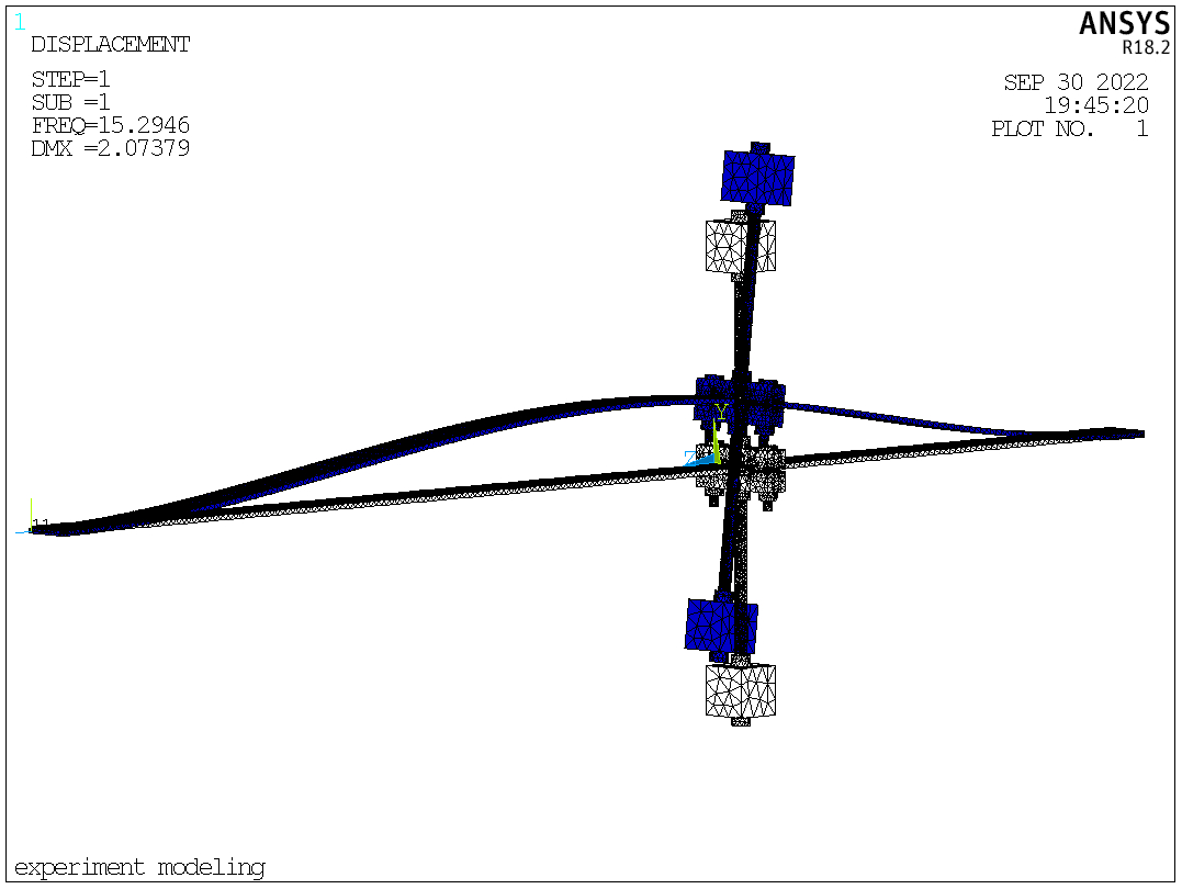
The 1st mode shape
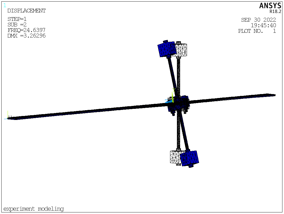
The 2nd mode shape
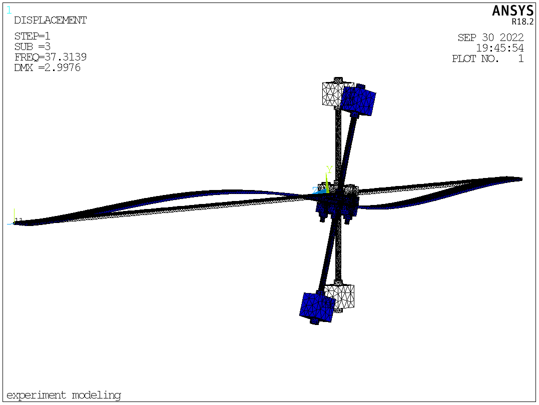
The 3rd mode shape
