In this post, we are going to explore the application of CONTA174 (i.e. 3D 8-node face-face contact element). CONTA174 is used to represent contact and sliding between 3D target surfaces and a deformable surface defined by this element. It can be used for both pair-based contact and general contact. In the case of pair-based contact, the target surface is defined by the 3D target element type, TARGE170. In the case of general contact, the target surface can be defined by CONTA174 elements (for deformable surfaces) or TARGE170 elements (for rigid bodies only).
An example of a bolted beam-column connection is given. Taking advantage of the symmetry, only half of the connection is analyzed (see Fig. 1). However, once the calculation is done, a larger graphic display can be created using /EXPAND, thus the stress results of the full model can be shown.
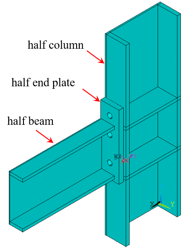
Fig. 1. Half of the geometry
The beam is welded to an end plate. The end plate is bolted to a column. The contact between the bolt head and column is bonded contact. Other contacts (between the end plate and column, between the nut and end plate, and between bolt and bolt hole) are defined as standard. This is achieved by defining KEYOPT(12) of CONTA174. The yield strength of the beam and column is 235MPa. The yield strength of the bolt is 400MPa. The yield strength of the end plate is 325MPa. The material model is assumed to be bilinear kinematic plasticity (BKIN). Although assuming there is a gap between the bolt and bolt hole, rigid-body motion is avoided by closing gap/reducing penetration with auto CNOF (as shown in the APDL). The upper and lower surfaces of the column are fixed. Distributed load is applied to the upper surface of the beam. The load and boundary conditions are shown in Fig. 2.
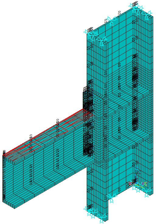
Fig. 2. Load and boundary conditions
To use mapped meshing, the volumes are divided before discretization (see Fig. 3). This is a time-consuming but important process. Some examples have been given in this post regarding the techniques of mapped meshing. The discretization of the half model is shown in Fig. 2.
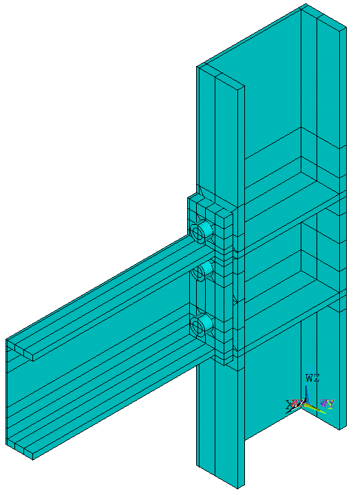
Fig. 3. Dividing volumes before mapped meshing
The APDL of this example is as follows (annotations are in lowercase).
FINISH
/CLEAR
/TITLE, BEAM COLUMN END PLATE CONNECTION (HALF MODEL)
/PREP7
!define beam parameters (unit:mm):
BT1=12			!beam flange thickness
BT2=8			!beam web thickness
BH=200			!beam height
BW=120			!beam width
BL=2*BH			!beam length
!define column parameters:
CT1=16			!column flange thickness
CT2=12			!column web thickness
CH=240			!column height
CW=180			!column width
!define the parameters of the end plate:
EPT=20			!end plate thickness
EPW=160			!end plate width
EPH=280			!end plate height
CL=2*CH+EPH		!column height
!define the parameters of the bolt hole, bolt, and nut:
BHD=21			!bolt hole diameter
BD=20			!holt diameter
BHT=13			!bolt head thickness
NT=18			!nut thickness
BHND=33			!the diameter of bolt head and nut
!define the parameters for bolt positioning:
DISH=80			!horizontal distance between bolt holes
DISV1=72		!vertical distance between bolt holes
DISV2=106		!vertical distance between bolt holes
DISV3=40		!vertical distance between bolt holes
DISPP1=10		!the positioning dimension between beam and end plate
NTX1=CH+EPT+NT	!the x coordinate of the center of the first nut
NTY1=DISH/2		!the y coordinate of the center of the first nut
NTZ1=CH+DISPP1+BT1+DISV3	!the z coordinate of the center of the first nut

!create geometry:
!column:
/VIEW,1,1,1,1
/ANGLE,1,-120,ZS,1
BLC4,,,CT1,CW/2,CL
VGEN,2,1,,,CH-CT1
BLC4,,,CH,CT2/2,CL
WPOFFS,,,CH+DISPP1
BLC4,,,CH,CW/2,BT1
VGEN,2,4,,,,,BH-BT1
VOVLAP,ALL
NUMCMP,ALL
!beam and end plate:
VSEL,NONE
WPCSYS,-1
WPOFFS,CH,,CH+DISPP1
BLC4,,,BL+EPT,BW/2,BT1
V1=VLINQR(0,14)		!return highest volume number defined, for more info about inquiry functions: https://ansys.netlify.app/html/inquiry/#john-crawford
VGEN,2,V1,,,,,BH-BT1
BLC4,,,BL+EPT,BT2/2,BH
WPOFFS,,,-DISPP1
BLC4,,,EPT,EPW/2,EPH
VOVLAP,ALL
NUMCMP,ALL
!bolt holes:
VSEL,NONE
WPCSYS,-1
WPOFFS,CH-2*CT1,DISH/2,NTZ1
WPROTA,,,90
CYL4,,,BHD/2,,,,BL
V1=VLINQR(0,14)
VGEN,2,V1,,,,,DISV2
VGEN,2,V1,,,,,DISV2+DISV1
CM,HVOLU,VOLU
VSEL,S,LOC,X,CH-CT1,CH+EPT
CM,VLS,VOLU
VSEL,ALL
VSBV,VLS,HVOLU
VSEL,ALL
NUMCMP,ALL
VPLOT
!divide the column (for mapped meshing):
VSEL,S,LOC,X,0,CH
WPCSYS,-1
WPOFFS,,,CH-CT1
VSBW,ALL
WPOFFS,,,NTZ1-CH+CT1
VSBW,ALL
WPOFFS,,,DISV2/2
VSBW,ALL
WPOFFS,,,DISV2/2
VSBW,ALL
WPOFFS,,,DISV1
VSBW,ALL
WPCSYS,-1
WPOFFS,,,CH+EPH+CT1
VSBW,ALL
WPOFFS,,DISH/2
WPROTA,,90
VSBW,ALL
NUMCMP,ALL
!divide the volume associated with bolt hole:
WPCSYS,-1
KWPAVE,27
WPROTA,,143
VSBW,84
KWPAVE,174
WPROTA,,-23
VSBW,82
!!!
WPCSYS,-1
KWPAVE,59
WPROTA,,51
VSBW,81
KWPAVE,179
WPROTA,,-4
VSBW,85
!!!
WPCSYS,-1
KWPAVE,179
WPROTA,,133
VSBW,88
KWPAVE,69
WPROTA,,7
VSBW,83
!!!
WPCSYS,-1
KWPAVE,174
WPROTA,,60
VSBW,86
KWPAVE,31
WPROTA,,-32
VSBW,87
!!!
WPCSYS,-1
KWPAVE,35
WPROTA,,152
VSBW,92
KWPAVE,222
WPROTA,,-32
VSBW,91
!!!
WPCSYS,-1
KWPAVE,54
WPROTA,,40
VSBW,89
KWPAVE,223
WPROTA,,9
VSBW,90
VSEL,ALL
NUMCMP,ALL
!divide the beam
VSEL,S,LOC,X,CH,2*BL
WPCSYS,-1
WPOFFS,,,NTZ1
VSBW,ALL
QXD=(BW-DISH)/2
WPOFFS,,,QXD
VSBW,ALL
WPOFFS,,,-2*QXD
VSBW,ALL
WPOFFS,,,DISV2
VSBW,ALL
WPOFFS,,,QXD
VSBW,ALL
WPOFFS,,,QXD
VSBW,ALL
WPOFFS,,,DISV1-2*QXD
VSBW,ALL
WPOFFS,,,QXD
VSBW,ALL
WPOFFS,,,QXD
VSBW,ALL
WPOFFS,,DISH/2
WPROTA,,90
VSBW,ALL
WPOFFS,,,-QXD
VSBW,ALL
WPOFFS,,,2*QXD
VSBW,ALL
!divide end plate
VSEL,S,LOC,X,CH,CH+EPT
WPCSYS,-1
WPOFFS,,,CH+DISPP1
VSBW,ALL
WPOFFS,,,BT1
VSBW,ALL
WPOFFS,,,BH-2*BT1
VSBW,ALL
WPOFFS,,,BT1
VSBW,ALL
WPOFFS,,BT2/2
WPROTA,,90
VSBW,ALL
NUMCMP,ALL
!divide the volume associated with bolt hole:
LSEL,S,RADIUS,,BHD/2
ASLL,S
VSLA,S
LSEL,ALL
ASEL,ALL
VSEL,R,LOC,X,CH,CH+EPT
WPCSYS,-1
KWPAVE,438
WPROTA,,45
VSBW,ALL
KWPAVE,440
VSBW,ALL
KWPAVE,444
VSBW,ALL
WPCSYS,-1
KWPAVE,432
WPROTA,,-45
VSBW,ALL
KWPAVE,436
VSBW,ALL
KWPAVE,416
VSBW,ALL
WPCSYS,-1
ALLSEL,ALL
NUMCMP,ALL
!define components:
VSEL,S,LOC,X,0,CH
CM,VCOLU,VOLU
VSEL,S,LOC,X,CH,CH+EPT
CM,VEP,VOLU
VSEL,S,LOC,X,CH+EPT,2*BL
CM,VBEAM,VOLU
!bolts:
VSEL,NONE
WPOFFS,NTX1,NTY1,NTZ1
WPROTA,,,-90
CYL4,,,BHND/2,,,,NT
CYL4,,,BD/2,,,,NT+EPT+CT1+BHT
WPOFFS,,,NT+EPT+CT1
CYL4,,,BHND/2,,,,BHT
VOVLAP,ALL
WPROTA,,90
VSBW,ALL
WPROTA,,,90
VSBW,ALL
CM,VBOLT,VOLU
VGEN,2,VBOLT,,,,,DISV2
VGEN,2,VBOLT,,,,,DISV2+DISV1
CM,VBOLT,VOLU
ALLSEL,ALL
NUMCMP,ALL
WPCSYS,-1

!define element types and material properties:
ET,1,SOLID185
MP,EX,1,2.1E5
MP,PRXY,1,0.3
TB,BKIN,1
TBDATA,1,235		!for beam and column
MP,EX,2,2.2E5
MP,PRXY,2,0.25
TB,BKIN,2
TBDATA,1,400 		!for bolts
MP,EX,3,2.1E5
MP,PRXY,3,0.28
TB,BKIN,3
TBDATA,1,325		!for end plate
R,1
R,2
R,3

!mesh:
CMSEL,S,VBOLT
VATT,2,2,1
MSHKEY,1
ESIZE,8
VMESH,ALL
CMSEL,S,VEP
VATT,3,3,1
ESIZE,10
VMESH,ALL
CMSEL,S,VBEAM
VATT,1,1,1
LSEL,S,LENGTH,,BL
LESIZE,ALL,50
LSEL,ALL
ESIZE,10
VMESH,ALL
CMSEL,S,VCOLU
LSEL,S,LENGTH,,CH-CT1
LESIZE,ALL,30
LSEL,S,LENGTH,,CH-2*CT1
LESIZE,ALL,40
LSEL,ALL
ESIZE,10
VMESH,ALL
ALLSEL,ALL

!define contact elements and target elements:
ET,2,CONTA174
ET,3,TARGE170
ET,4,CONTA174
ET,5,CONTA174
KEYOPT,4,12,3			!behavior of contact surface: bonded
KEYOPT,5,5,3			!close gap/reduce penetration with auto CNOF (contact surface offset)
DFKN=1.0				!normal penalty stiffness factor
DFTO=0.01				!penetration tolerance factor

!define contact pairs:
!between end plate and column (standard):
R,4,,,DFKN,DFTO
CMSEL,S,VEP
NSLV,S,1
NSEL,R,LOC,X,CH
REAL,4
TYPE,2
ESURF
CMSEL,S,VCOLU
NSLV,S,1
NSEL,R,LOC,X,CH
NSEL,R,LOC,Z,CH-CT1,CH+EPH+CT1
TYPE,3
ESURF
!for bolts:
NTZ2=NTZ1+DISV2			!the position of the 2nd bolt hole
NTZ3=NTZ2+DISV1			!the position of the 3rd bolt hole
*DO,IBOLT,1,3
	NTZI=NTZ%IBOLT%
	MNI1=2+3*IBOLT
	MNI2=3+3*IBOLT
	MNI3=4+3*IBOLT
	!between nut and end plate (standard):
	R,MNI1,,,DFKN,DFTO
	LSEL,S,RADIUS,,BHND/2
	LSEL,R,LOC,Z,NTZI-BHND/2,NTZI+BHND/2
	LSEL,R,LOC,X,NTX1-NT
	ASLL,S
	ASEL,R,LOC,X,NTX1-NT
	LSEL,ALL
	NSLA,S,1
	REAL,MNI1
	TYPE,2
	ESURF
	LSEL,S,RADIUS,,BHD/2
	LSEL,R,LOC,Z,NTZI-BHD/2,NTZI+BHD/2
	LSEL,R,LOC,X,NTX1-NT
	ASLL,S
	ASEL,R,LOC,X,NTX1-NT
	LSEL,ALL
	NSLA,S,1
	TYPE,3
	ESURF
	!between bolt and bolt hole (standard):
	R,MNI2,,,DFKN,DFTO
	LSEL,S,RADIUS,,BD/2
	LSEL,R,LOC,Z,NTZI-BD/2,NTZI+BD/2
	ASLL,S
	ASEL,R,LOC,X,CH-CT1,CH+EPT
	ASEL,U,LOC,X,CH-CT1
	ASEL,U,LOC,X,CH+EPT
	LSEL,ALL
	NSLA,S,1
	REAL,MNI2
	TYPE,5
	ESURF
	LSEL,S,RADIUS,,BHD/2
	LSEL,R,LOC,Z,NTZI-BD/2,NTZI+BD/2
	ASLL,S
	LSEL,ALL
	ASEL,U,LOC,X,CH
	ASEL,U,LOC,X,CH+EPT
	ASEL,U,LOC,X,CH-CT1
	NSLA,S,1
	TYPE,3
	ESURF
	!between bolt head and column (bonded):
	R,MNI3,,,DFKN,DFTO
	LSEL,S,RADIUS,,BHND/2
	LSEL,R,LOC,Z,NTZI-BHND/2,NTZI+BHND/2
	LSEL,R,LOC,X,CH-CT1
	ASLL,S
	ASEL,R,LOC,X,CH-CT1
	LSEL,ALL
	NSLA,S,1
	REAL,MNI3
	TYPE,4
	ESURF
	LSEL,S,RADIUS,,BHD/2
	LSEL,R,LOC,Z,NTZI-BHD/2,NTZI+BHD/2
	LSEL,R,LOC,X,CH-CT1
	ASLL,S
	ASEL,R,LOC,X,CH-CT1
	LSEL,ALL
	NSLA,S,1
	TYPE,3
	ESURF
*ENDDO

!boundary conditions:
ALLSEL,ALL
ASEL,S,LOC,Z,0
ASEL,A,LOC,Z,2*CH+EPH
DA,ALL,ALL
ASEL,S,LOC,Y,0
DA,ALL,SYMM
ASEL,S,LOC,Z,CH+DISPP1+BH
ASEL,R,LOC,X,CH+EPT,2*BL
SFA,ALL,1,PRES,6.5
ALLSEL,ALL

!solve
/SOLU
NLGEOM,ON
OUTRES,ALL,ALL
TIME,1
NSUBST,50
PRED,OFF
SOLVE

!post processing
/POST1
/EXPAND,2,RECT,HALF,,1E-6
PLDISP,1
CMSEL,S,VBEAM
ESLV
PLNSOL,S,X
CMSEL,S,VBOLT
ESLV
PLNSOL,S,EQV
PLNSOL,EPPL,EQV
CMSEL,S,VEP
ESLV
PLNSOL,S,EQV
PLNSOL,EPPL,EQV
CMSEL,S,VCOLU
ESLV
PLNSOL,S,EQV
PLNSOL,EPPL,EQV
ALLSEL,ALL
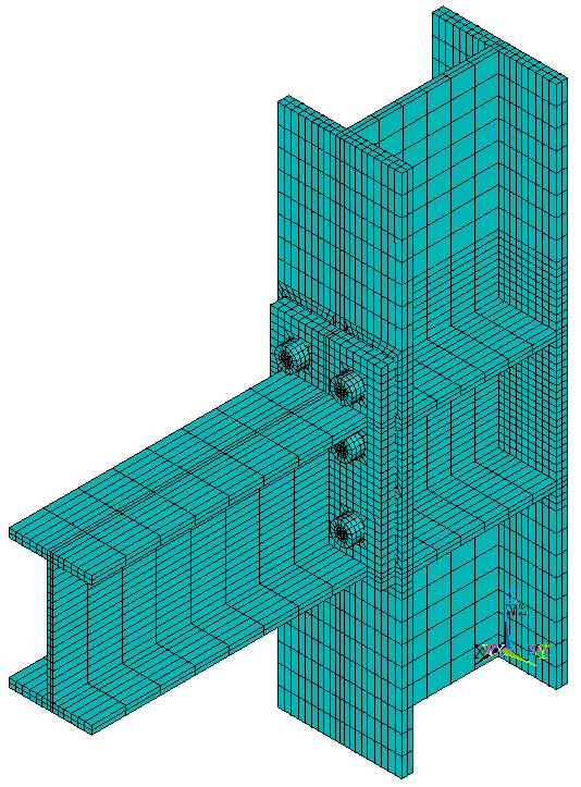
Fig. 4. Discretization: after expansion
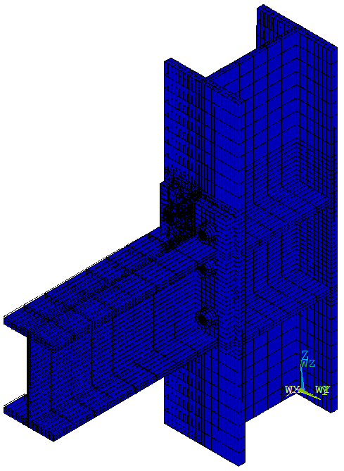
Fig. 5. Deformation
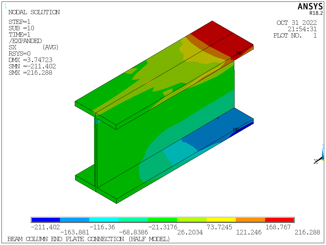
Fig. 6. Beam stress results (sigma_x)
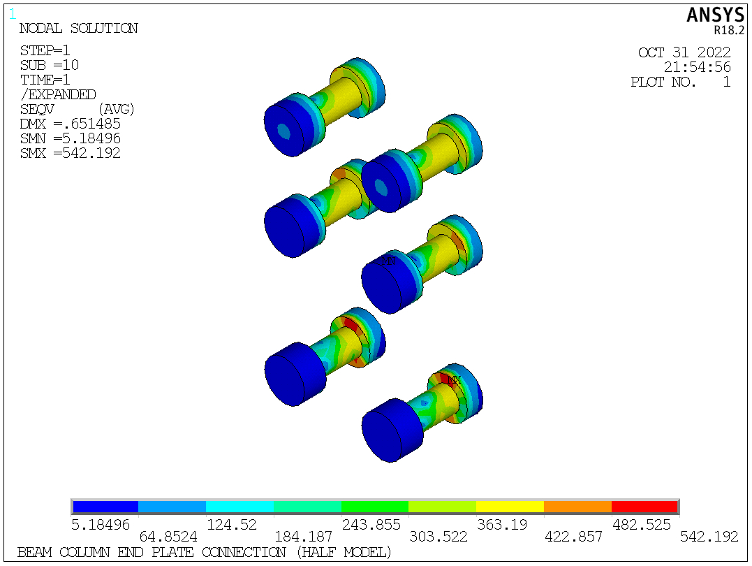
Fig. 7. Bolt equivalent stress
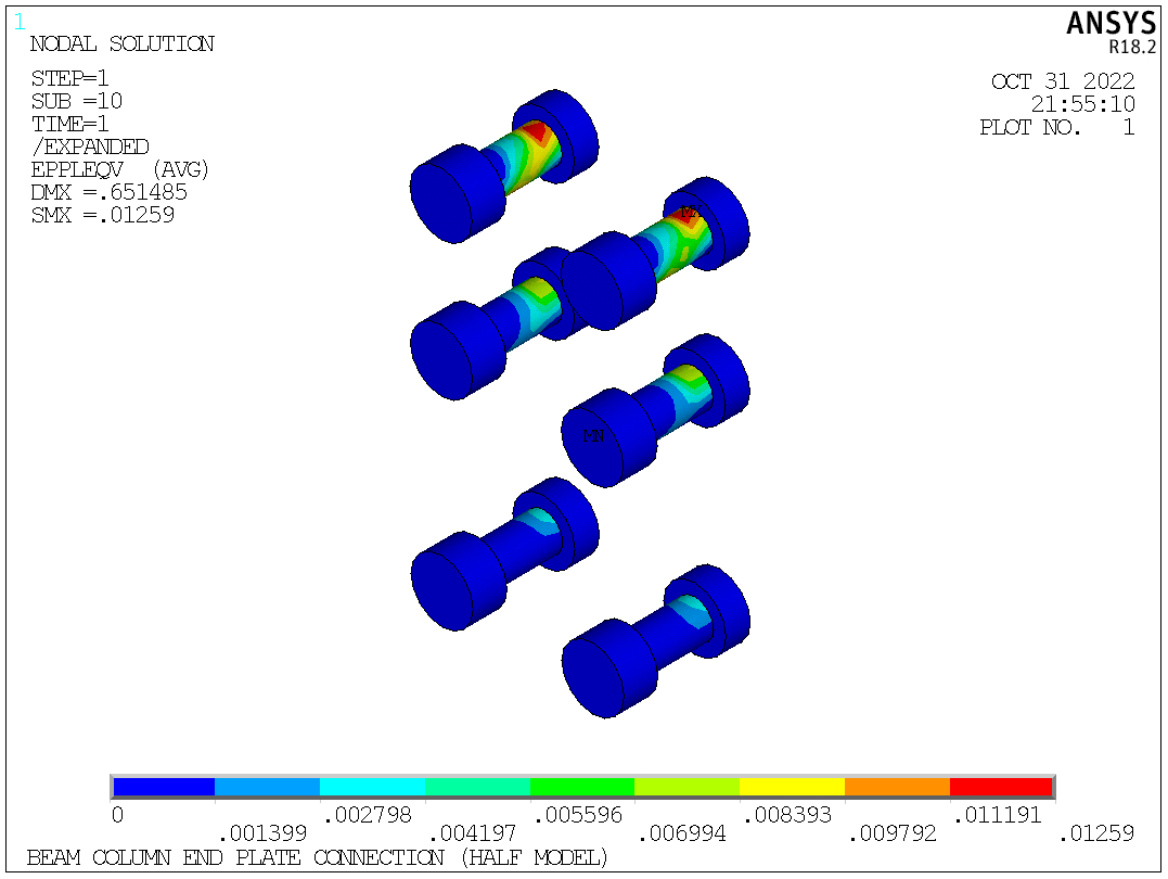
Fig. 8. Bolt plastic equivalent strain
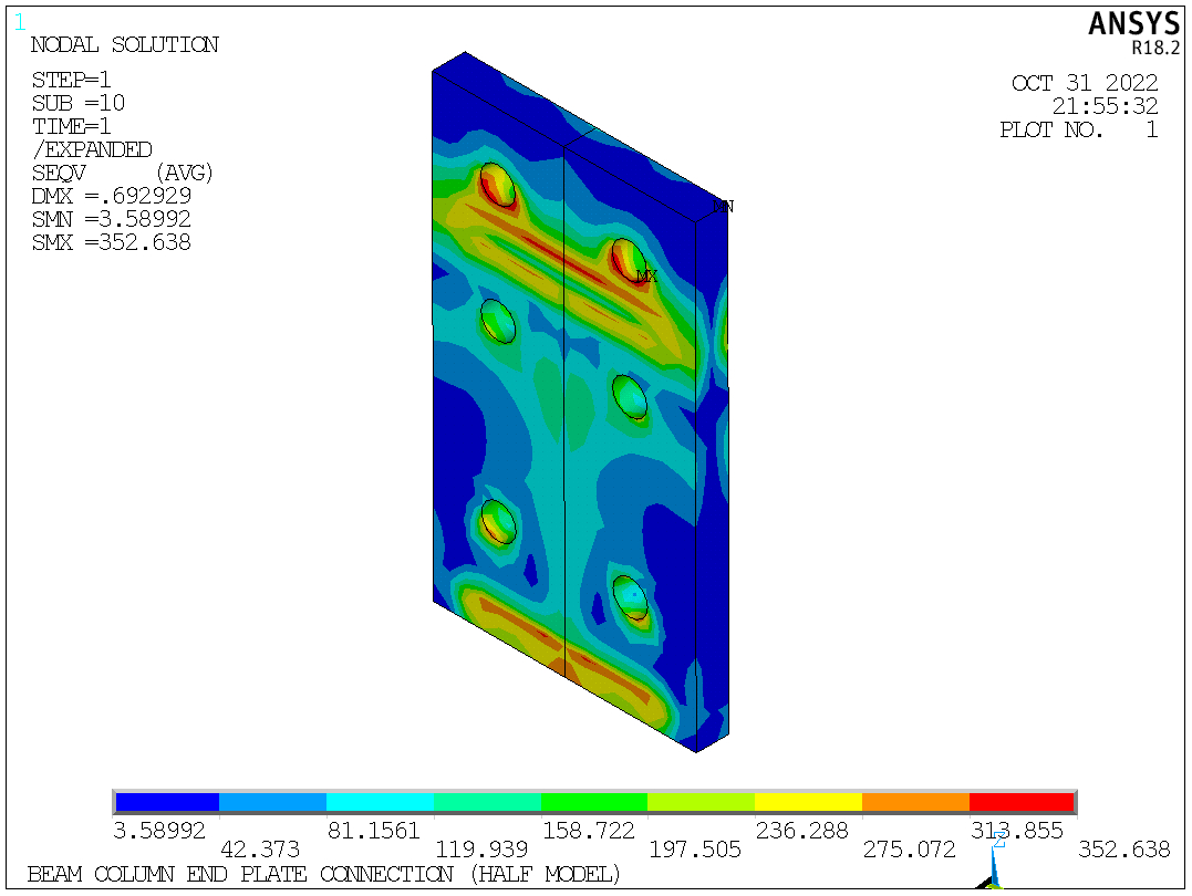
Fig. 9. End plate equivalent stress
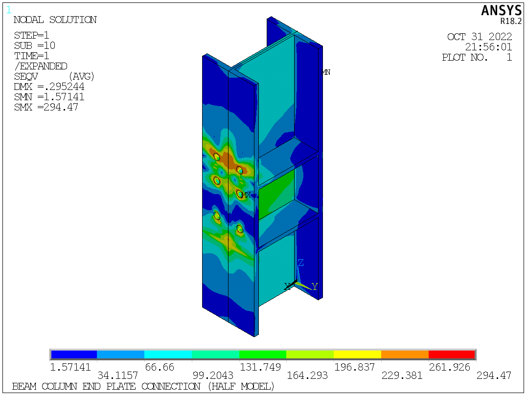
Fig. 10. Column equivalent stress
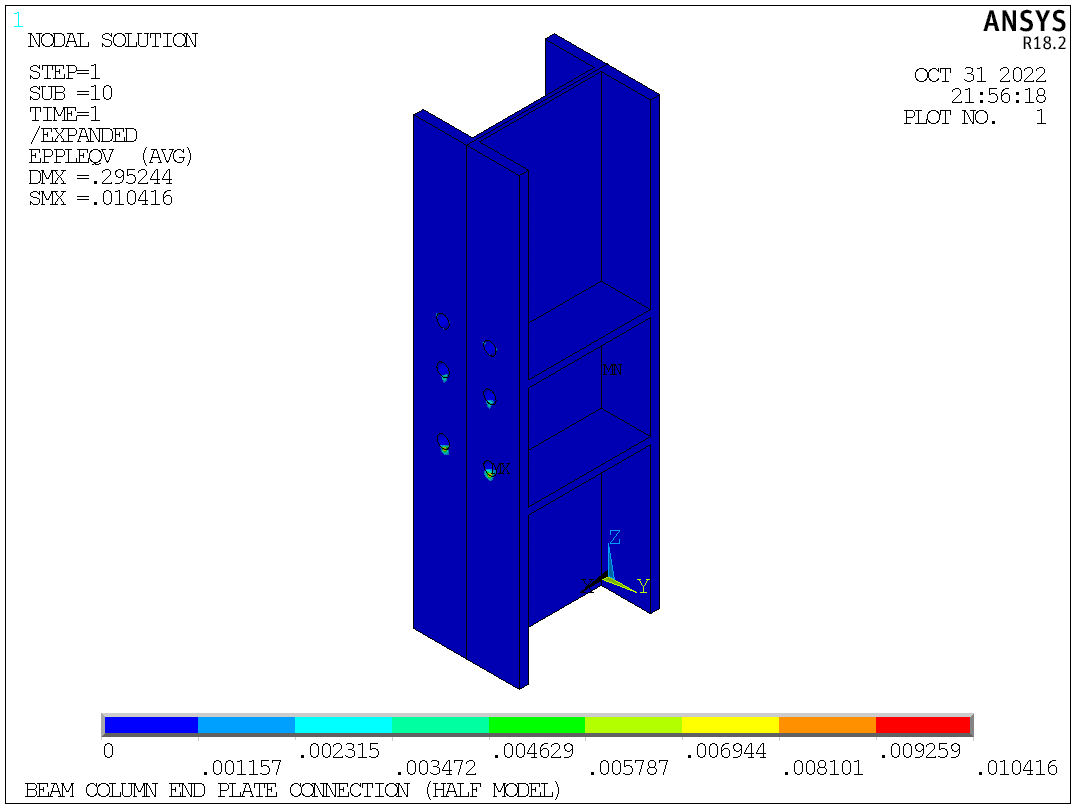
Fig. 11. Column plastic equivalent strain
