In geometric linearity, the equilibrium equation is established in the undeformed state and will not be updated with deformation. In other words, we ignore the small deformation of the geometry to simplify the calculation. This does not seem to be in line with the core idea of structural mechanics, because the calculation of deformation is the whole purpose of structural mechanics. However, in most engineering problems, the deformations are so small that deviations from the original geometry are imperceptible. The small error introduced by ignoring the deformations does not warrant the added mathematical complexity generated by a more sophisticated theory. This is why the vast majority of analysis are performed assuming geometric linearity.
In this post, we are going to analyze a two-member truss with a 20kN load applied to the middle:

The material is assumed to be elastic throughout the analysis with the modulus of elasticity being 200GPa. The displacement of the middle node and the axial forces are calculated in two circumstances: small deformation and large deformation (nonlinear geometry).
The APDL considering small deformation only is as follows (annotations are in lowercase)
FINISH
/CLEAR
/PREP7
ET,1,LINK180			!truss element
R,1,5E-4			!cross-sectional area, unit: m^2
MP,EX,1,2E11			!unit: Pa
MP,PRXY,1,0.3
N,1
N,2,1,-0.02
N,3,2,0
E,1,2
E,2,3
D,1,UX,,,3,2,UY
F,2,FY,-20E3			!unit: N
FINISH
!small displacement, linear analysis:
/SOLU
SOLVE
FINISH
/POST1
SET,LAST
PRNSOL,U,Y
ETABLE,AXIALF,SMISC,1
PRETAB,AXIALF
PLLS,AXIALF,AXIALF,1,0	        !axial force diagram
FINISH
Displacement=0.25015m

Axial force diagram (axial force=500100N)
Next the large deformation is considered
!large deformation, nonlinear geometry:
/SOLU
NLGEOM,ON
NSUBST,20
AUTOTS,OFF
OUTRES,ALL,ALL
SOLVE
FINISH
/POST1
SET,LAST
PRNSOL,U,Y
ETABLE,AXIALF,SMISC,1
PRETAB,AXIALF
PLLS,AXIALF,AXIALF,1,0	!axial force diagram
FINISH
/POST26
NUMVAR,200
RFORCE,2,1,F,Y,RFY1
NSOL,3,2,U,Y,UY2
PROD,100,2,,,,,,2		!RFY1 times 2=external load
ABS,101,3,,,,,,1
/AXLAB,X,Displacement(m)
/AXLAB,Y,P(N)
XVAR,101
PLVAR,100
FINISH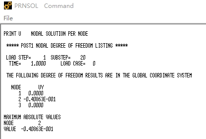
Displacement=0.040863m
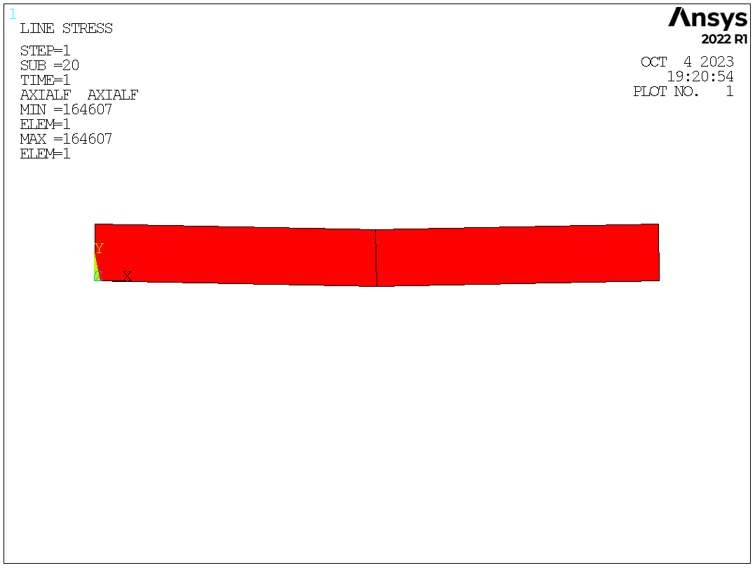
Axial force diagram (axial force=164607N)

Equilibrium path
From the equilibrium path, as the load increases, the stiffness increases as well, which indicates obvious nonlinearity. The real deformation and axial force are actually much smaller than what is predicted by the linear analysis. In this case, linear solutions are not qualified as a design reference.
| Displacement (m) | Axial force (N) | |
| Linear analysis | -0.25015 | 500100 |
| Nonlinear analysis | -0.040863 | 164607 |
