In this post, we are going to model a wood pallet as shown in Figure 1 using SolidWorks Simulation.
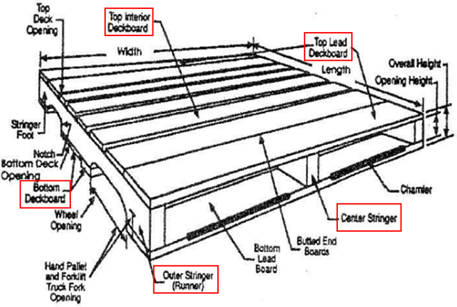
Figure 1 Schematic diagram of a typical stringer pallet with principal parts labeled.
Radiata pine is a popular choice for making wood pallets. It can be described as an orthotropic material, i.e. it has unique and independent mechanical properties in the directions of three mutually perpendicular axes (as shown in Figure 2). Its detailed material constants in the dry state are not readily available in the literature. This document uses the constants of red pine with 12% moisture content which has similar mechanical properties to those of radiata pine.

Figure 2 Three principal axes of wood with respect to grain direction and growth rings.
In SolidWorks, the mechanical properties of radiata pine can be customized as follows:

It should be noted that the modulus of rupture is taken as yield strength here, despite that wood materials do not feature a yield plateau during their deformation. Modulus of rupture reflects the maximum load-carrying capacity of a member in bending and is proportional to the maximum moment borne by the specimen. Modulus of rupture is an accepted criterion of strength, although it is not a true stress because the formula by which it is computed is valid only to the elastic limit.
After defining correct material properties, it is necessary to specify the fibre direction in each component. To do this, coordinate systems should be created in the assembly. These coordinate systems will be referenced later when assigning material properties to entities in simulation.
In this example, two coordinate systems were created for deckboards and stringers, respectively (see Figure 3). When assigning material properties to the model in simulation, select all components lying in the same direction then right-click to edit material, choose orthotropic material and select the coordinate system accordingly (see Figure 4).

(a) For deckboards

(b) For stringers
Figure 3 Defining coordinate systems for components in different directions.
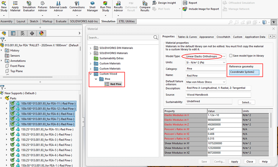
Figure 4 Material definition in Simulation.
Bonded contact was applied between deckboards and stringers, which means the FE model is stiffer than the actual pallet, potentially leading to higher estimates of stress and lower estimates of displacement. This should be noticed when interpreting results.
The freight is in contact with the third and fourth deckboards from either side of the pallet (see Figure 5). According to the geometry of the base of the freight, the contact areas can be determined and projected onto the surface of deckboards. These are the areas on which the weight of the freight is loaded. This was done by splitting deckboard surface using split lines (as shown in Figure 6).

Figure 5 Deckboards that are holding the freight.

Figure 6 Drawing split lines on the surface of deckboard.
Similarly, the contact areas between forklift and pallet can be determined after measuring the dimensions of forks. Using split lines, these areas can be obtained on the bottom side of the deckboards (see Figure 7), and boundary conditions can be applied to them.

Figure 7 Contact areas between forks and pallet.
Figure 8 shows the curvature-based solid mesh. A total of 61932 solid elements were generated.

Figure 8 Meshing.
The results are as follows.

Figure 9 Resultant displacement.

Figure 10 The 1st principal stress.

Figure 11 Normal stress in X direction.

Figure 12 Shear stress in XY plane.
From the above results, the maximum resultant displacement is around 0.143mm. The maximum values of Sigma_1 and Sigma_x are very close (1.97MPa and 1.96MPa, respectively) and below yield strength (i.e. modulus of rupture). The maximum Tau_xy is about 0.969MPa, which is below the shear strength in XY 4.76MPa. Overall, the current wood pallet design is safe enough for this boundary condition. Those deckboards that contact the freight directly experience the maximum stress.
It is worth mentioning that when interpreting stress results, the direction should be referenced to the global coordinate system. In this case, Sigma_x shows the normal stress in deckboards, while Sigma_z represents the normal stress in stringers.
