What is harmonic response analysis?
Let’s start this post by a simple example: A single degree of freedom oscillator loaded with a time varying force F.
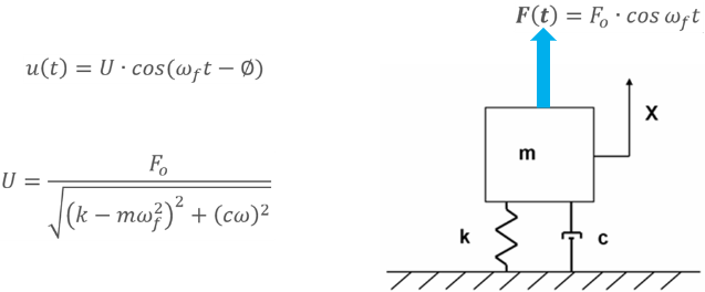
The solution to this problem is known in closed form. If the force F oscillates, the resulting displacement will oscillate in the same oscillatory fashion. The phase angle Φ, or delay in the system response, is due to damping. The important thing to note is that this solution is valid once the system reaches the stable oscillatory state. It should be noted that when the force F is suddenly applied, disturbance oscillations in the system will occur. These disturbance oscillations decay with time due to damping, and eventually all that is left is the solution shown above.
From the above example, we can see although you can create a modal time history study and define loads as functions of time, you may not be interested in the transient variation of the response with time. In such cases, you save time and resources by solving for the steady-state peak response at the desired operational frequency range using harmonic analysis. Harmonic analysis provides an elegant solution where the loading is oscillatory, in the form of a sin or cos functions.
Because the solution oscillates at the same frequency as the operating frequency of the force, transient solutions are not required. As a consequence:
- Harmonic study input is not transient. It is always provided in the form of load amplitudes versus its operating frequency. Harmonic study therefore solves for a range of harmonic loads, not just one specific load.
- Harmonic study only provides amplitudes of the resulting quantities (e.g. peak amplitudes of stresses, displacements, accelerations, and velocities), as well as response graphs of phase angles of response parameters over the range of operating frequencies.
Harmonic Loading
In a general case, the force is specified as a function of its operating frequency ωf rather than time. Because the system oscillates in the same harmonic fashion as the loading force, all that we really need to know to safely design the product is the displacement amplitude U.
To summarize, in a harmonic simulation, applied load is a harmonic function. The two parameters characterizing it are: the force amplitude F0, and the operating frequency ωf. The displacement output would then be an oscillatory harmonic function characterized by the same frequency ωf and the displacement amplitude U.
If we view both input and output in graphs, the input is the force amplitude F0 versus the operating frequency ωf. The output is the displacement amplitude U versus the same operating frequency ωf.

Therefore, harmonic study does not solve for one load only. It solves for the range of the force amplitudes across its operating frequency range, and the solution is variation of displacement amplitudes across the same operating range of the frequency. Same amplitude output is also provided for all other quantities such as velocities, accelerations, strains, and stresses. In SolidWorks Simulation, the force load can be specified as a table of the force amplitudes against the corresponding operating frequency.
