Conjugate heat transfer is the combination of convection and conduction heat exchange. By default, SolidWorks Flow Simulation considers the heat transfer due to convection within a fluid, however, it does not consider conduction through solids. This option must be selected when defining the analysis type in the Wizard (see Figure 2).
For example, in this problem, a heated cold plate sits in an open air-filled environment. Heat is generated at 200W on the top surface of the plate. The plate is cooled by a cooling tube as shown in Figure 1. The tube contains R-123 at -5 °C flowing at 0.001kg/s through the inlet. Determine the steady state temperature distribution through the plate and the surrounding air.
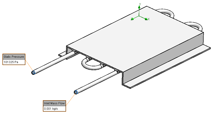
Figure 1. Problem description.
For this problem, materials for both solid and fluid should be defined using the Wizard. Besides, there are two types of fluid i.e. air and R-123. R-123 is a predefined fluid in the Engineering Database, however, it is considered as Real Gases in the software (see Figure 3).
Apart from the Navier-Stokes equations, SW Flow Simulation also uses state equations to solve its problems. In general, gases are considered ideal, which means that the size of the gas molecules is neglected. The intermolecular forces between molecules are also neglected. This allows the pressure in the gas to be directly related to the temperature.
If the considered gas gets near the gas-liquid phase transition or above the critical point (i.e. becomes supercritical fluid), the ideal gas state equation can no longer describe the gas behaviour properly (e.g. the Joule-Thomson effect) due to the increased intermolecular forces affecting the pressure. A real gas fluid should be selected from the Engineering Database, so that the real gas state equations are used. SW Flow Simulation allows users to use real gases in a broad range of parameters, including both sub- and supercritical regions.
The general settings for analysis type and fluids in the Wizard are shown in Figure 2 and Figure 3, respectively. Aluminium is taken as the solid material.

Figure 2. Settings for analysis type.

Figure 3. Settings for fluids.
When multiple fluids are specified in the project, fluid subdomains have to be assigned to them. Any cavity without a fluid subdomain assignment is assumed to be filled with the default fluid. In this problem, the fluid subdomain for R-123 is defined by selecting an internal face of the tube that is filled with R-123, as shown in Figure 4.

Figure 4. Fluid subdomain for R-123.
Some results are listed below.
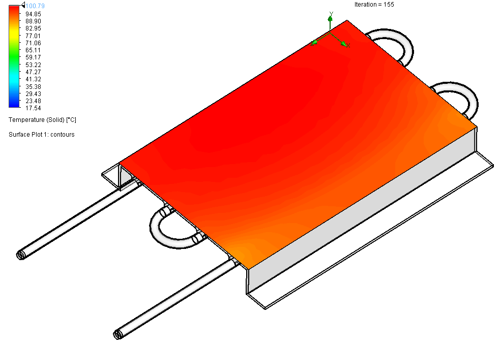
Figure 5. Temperature (solid) surface plot.
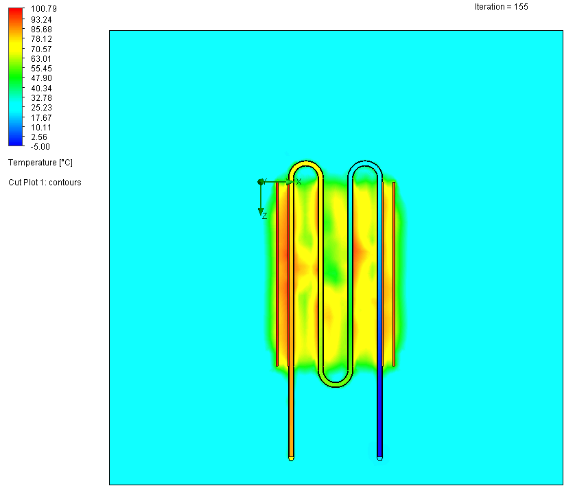
Figure 6. Temperature cut plot.

Figure 7. Temperature cut plot (cut vertically along the outlet pipe).

Pingback: A Heat Exchanger in SolidWorks Flow Simulation | Xutao Sun