The chassis is a major part in any automotive design since it is the structural backbone of various functional systems attached to it and is responsible for carrying loads of different components. Using ANSYS Mechanical to analyse a chassis allows different design configurations to be evaluated efficiently, making it possible to assess stiffness and deformation behaviour, helping engineers achieve an optimal balance between structural performance and manufacturing cost.
In this post, we are going to introduce two representative student competition chassis designs: the Baja SAE chassis and the Formula SAE chassis, and briefly discuss the frontal impact analysis approaches.
Baja SAE chassis
Figure 1 shows the original chassis model imported into SpaceClaim. The model can be created in a standard CAD environment, for example using weldments in SolidWorks. A clean, error-free CAD model significantly simplifies geometry preparation and improves robustness during subsequent processing in SpaceClaim.
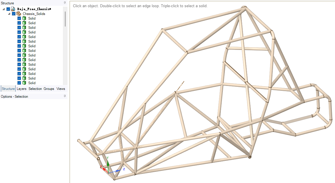
Figure 1. The solid model of a Baja SAE chassis.
After importing the original CAD model into SpaceClaim, you can either extract surfaces from the solid geometry for shell modelling in Mechanical, or extract beam representations for beam modelling. Figure 2 shows the extracted beam model. Beam profiles are generated automatically from the solid CAD; however, they can be manually redefined to override the default assignments, as illustrated in Figure 3.
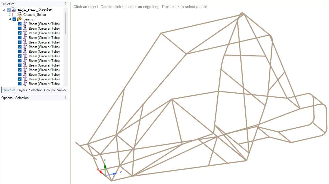
Figure 2. The extracted beams.
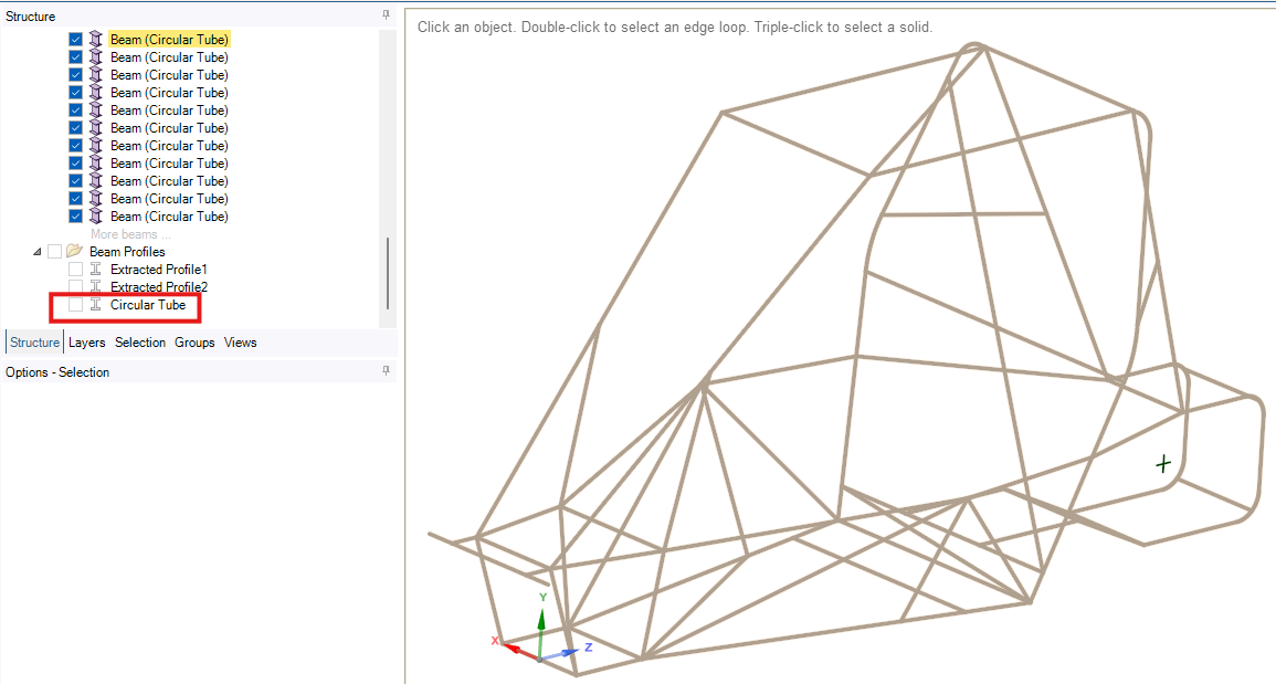
Figure 3. Define the circular tube profile.
Formula SAE Chassis
Figure 4 shows a Formula SAE chassis with suspension arms extracted from the solid CAD. This model is more complex, and as shown in Figure 5, joints and springs are included to represent the interactions between the suspension arms and the chassis. In addition, point masses are added to represent the driver and engine.
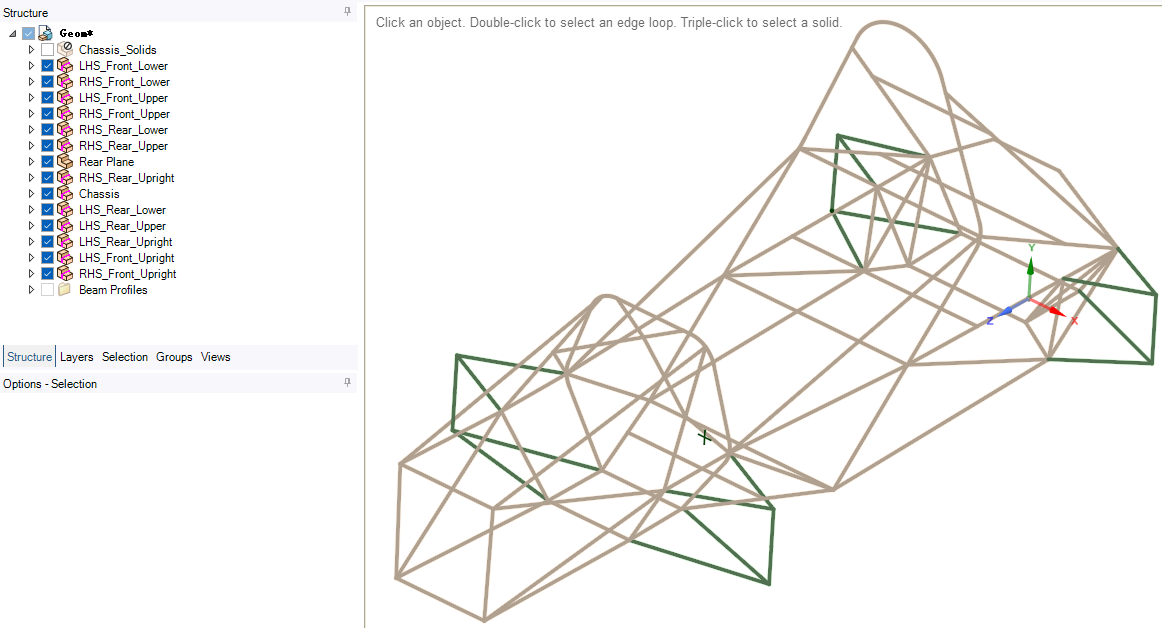
Figure 4. The extracted beams of a formula SAE chassis with suspension arms.
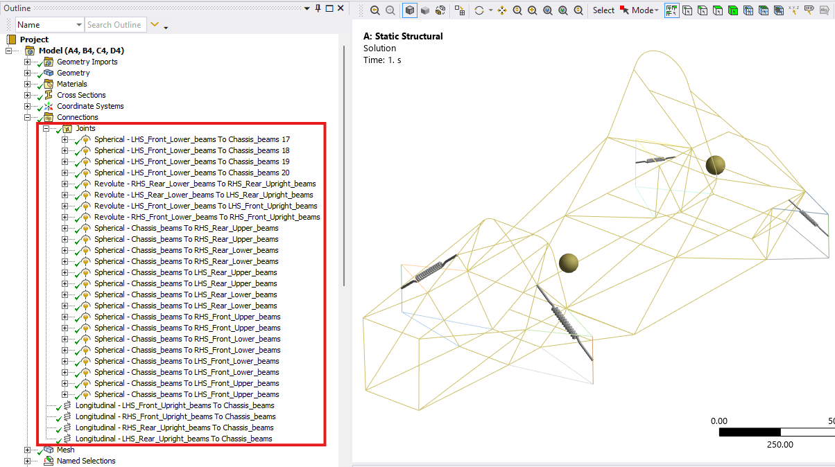
Figure 5. Joint and spring connections.
Frontal Impact Analysis
First, a frontal impact scenario is examined using static analysis. For the Baja SAE chassis, the default Structural Steel material is used, and Large Deflection is disabled in the analysis settings, meaning all nonlinear effects are excluded. As a result, the simulation provides only a preliminary overview of the structural response under the specified boundary conditions.
An impact force is applied to the front member (Figure 6) and the fire wall behind the driver seat is fixed (Figure 7). From Figure 8, the maximum stress happens near the fixed support.
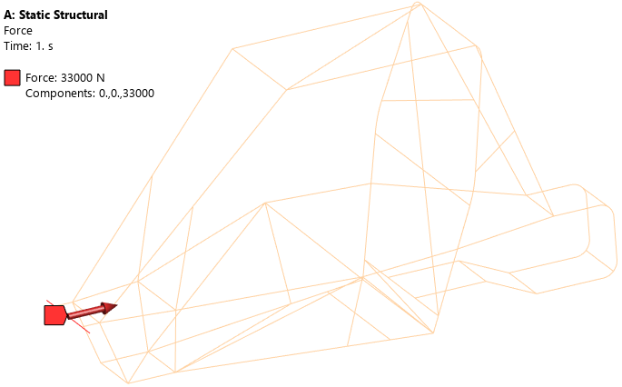
Figure 6. Apply the impact force to the front member.
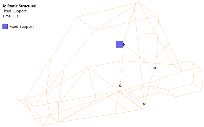
Figure 7. Keep the fire wall behind driver seat fixed.
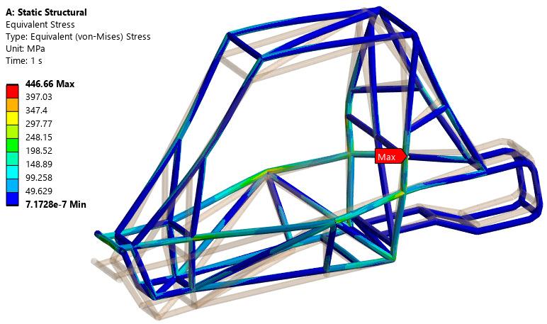
Figure 8. Stress distribution.
For the formula SAE chassis, an impact force is applied to the four nodes on the front bulkhead (Figure 9) and the other four nodes on the rear structure are simply supported, corresponding to the suspension mounting points (Figure 10). From Figure 11, the maximum stress also occurs near the rear supports.
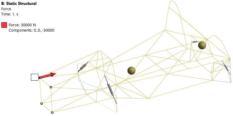
Figure 9. Apply the impact force to the front bulkhead.
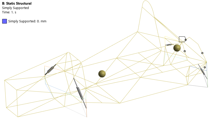
Figure 10. Simply supported boundaries on the rear structure.
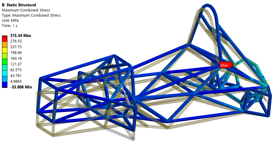
Figure 11. Stress distribution.
As a comparison, another Baja SAE chassis frontal impact event is simulated using LS-DYNA. Surfaces are extracted from the solid CAD and shell elements are used in the simulation. When preparing the geometry, an additional flat surface is created (see Figure 13), which serves as the rigid stationary wall in the simulation. Structural Steel with bilinear isotropic hardening is used, and the corresponding stress-strain curve is shown in Figure 12.
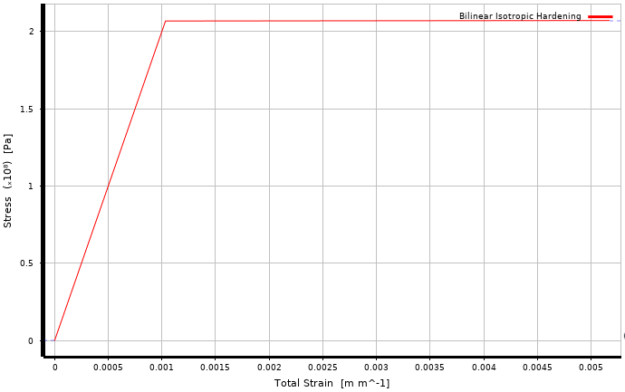
Figure 12. Stress-strain curve.
As shown in Figure 13, a point mass representing the driver is defined and assigned to the seat belt attaching surfaces. The rigid wall is fixed (Figure 14) and an initial velocity is assigned to the chassis (Figure 15).
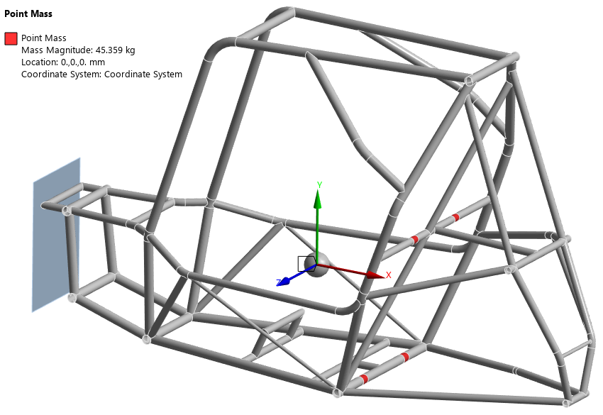
Figure 13. Driver point mass.

Figure 14. Fixed wall.

Figure 15. Initial velocity.
Figure 16 shows that the maximum stress occurs near the seat belt attachment surfaces. The stress reaches the yield limit, indicating the onset of plastic deformation and permanent damage. Compared with the previous static analysis, this simulation is able to capture the failure mode near the front bulkhead (see Figure 17).
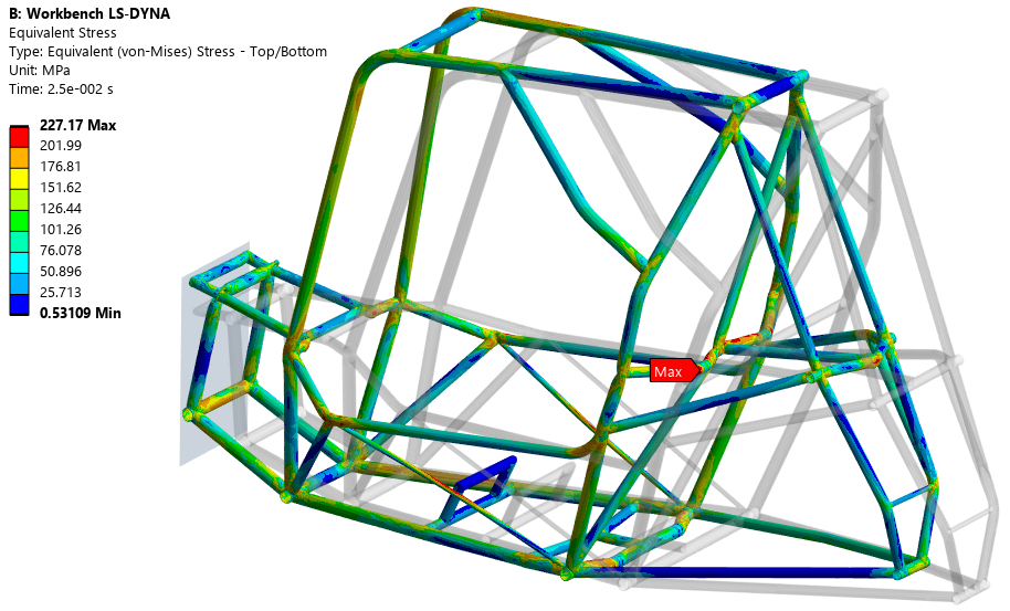
Figure 16. Stress distribution.

Figure 17. Frontal failure.
Overall, static analysis can be useful for preliminary stiffness and load-path assessment, but it is not suitable for predicting impact-induced damage. Explicit dynamic simulation is required to capture plastic deformation and failure modes in chassis impact scenarios. The LS-DYNA model can be further refined to improve the accuracy and fidelity of the results.
