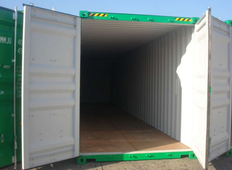
Fig.1. A typical container
This problem is to analyze the torsional limit of an open container (without lid). It is a typical problem in structural nonlinear buckling analysis. As an alternative to the Newton-Raphson method, the arc-length method will be used.

Fig.2. A simplified model of the container body
Some assumptions and simplifications in this problem:
- During the torsional deformation, the container body deforms, but the shape of two ends remain rectangular.
- The front end is simply supported, and the torque is applied to the rear end (as shown in Fig. 3 and Fig. 4).
- To maintain the rectangular shape of the rear end meanwhile exert the torque, an elastic plate is fixed onto the rear end and the torque is applied to the elastic plate.
- The torque is exerted through forces of opposite direction acting on opposing edges.

Fig.3. Front end
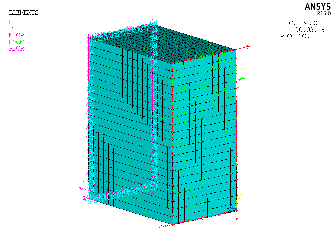
Fig.4. Rear end
Some challenges in this problem:
- The application of the arc-length method.
- The comparison between the Newton-Raphson method and the arc-length method. Ideally, some results calculated using the former method are helpful to estimate the torsional limit (even if the convergence issue happens in the end).
- How to evaluate the accuracy of results.
- The balance between accuracy and the cost of computation.
The APDL of this problem is as follows:
FINISH
/CLEAR
/FILNAME,111

!units: N, mm, Mpa
!define parameters
EXX=207E3
B=2050			!width
H=4140			!height
L=3270			!length
ELEMENT_L=200		!element length
F=6E6
M=F*(B+H)/1000		!unit: N*m

!define element type and material property
/PREP7
ET,1,SHELL143
R,1,12			!thickness
R,2,25			!the thickness of loading board
MP,EX,1,EXX
MP,PRXY,1,0.27
TB,BISO,1,1,2		!Bilinear isotropic hardening model for material 1, defined by two points
TBDATA,,313.6
MP,EX,2,2E7
MP,PRXY,2,0.3
TB,BISO,2,1,2		!Bilinear isotropic hardening model for material 2, defined by two points
TBDATA,,3000

!create geometry
BLOCK,0,B,O,H,0,L
VDELE,1
ADELE,2,,,1
APLOT

!meshing
ASEL,S,,,3,6,1
AATT,1,1,1
ASEL,S,,,1
AATT,2,2,1
ALLSEL
AESIZE,ALL,ELEMENT_L
AMESH,ALL

!define BCs and loads
NSEL,S,LOC,Z,L
D,ALL,UX,0,,,,UY,UZ
NSEL,S,LOC,Z,0
NSEL,R,LOC,Y,0
*GET,COUNT_X,NODE,,COUNT
F,ALL,FX,F/COUNT_X
NSEL,S,LOC,Z,0
NSEL,R,LOC,Y,H
F,ALL,FX,-F/COUNT_X
NSEL,S,LOC,Z,0
NSEL,R,LOC,X,0
*GET,COUNT_Y,NODE,,COUNT
F,ALL,FY,-F/COUNT_Y
NSEL,S,LOC,Z,0
NSEL,R,LOC,X,B
F,ALL,FY,F/COUNT_Y
ALLSEL

!solve
/SOLU
ANTYPE,STATIC
NLGEOM,ON
NSUBST,500
OUTRES,ALL,ALL
EQSLV,SPARSE
ARCLEN,ON		!the arc-length method
!ARCTRM,U,180,,UX	!Controls termination of the solution when the arc-length method is used
SOLVE

!post-processing
/POST1
SET,LAST
ESEL,U,MAT,,2
PLDISP,2
PLNSOL,S,EQV,0,1
ALLSEL
EPLOT

!time history post-processing
!based on the node at the center of the loading plate, draw a torque-rotation curve
/POST26
NSEL,S,LOC,X,B/2
NSEL,R,LOC,Y,H/2
*GET,COUNT_N,NODE,,COUNT
*IF,COUNT_N,EQ,0,THEN		!if there is no node at the geometric center, then select those nodes closest to the center
NSEL,S,LOC,X,B/2-ELEMENT_L,B/2+ELEMENT_L
NSEL,R,LOC,Y,H/2-ELEMENT_L,H/2+ELEMENT_L
*GET,COUNT_N,NODE,,COUNT
*ENDIF
!draw the curve
*GET,NNODE,NODE,,NUM,MAX
NSOL,2,NNODE,ROT,Z,ROTZ_2
PROD,3,1,,,,,,M		!time is variable 1 by default. time times M means shows the increase of torque throughout the process
/AXLAB,X,ROT(rad)
/AXLAB,Y,M(Nm)
XVAR,2
PLVAR,3
Fig.5. The deformed shape.

Fig.6. Von Mises stress

Fig.7. Torque-rotation curve
