In this post, we are going to analyze the stress and deformation of a rubber O ring as shown in the following figure.

The rubber O ring is often used for sealing purposes. It may be under large pressure and its deformation is constrained by the sealing groove. Due to the large difference in the rigidity between rubber and groove, the groove can be considered as rigid. Besides, both the O ring and loads are axisymmetric, the model can be simplified by analyzing the cross-section of the O ring.
In this example, the cross-section of the O ring is discretized using PLANE182 elements. The axisymmetric element behavior is employed. The face-face contact between the groove and O ring is modeled by contact pairs consisting of CONTA171 and TARGE169 elements. The contact elements in each contact pair share the same set of real constants. The three-term Ogden model is used to describe the hyperelastic material behavior of rubber.
The handling of axisymmetric geometry in ANSYS is as follows. Axisymmetric geometry is defined in the X-Y plane with positive X values. The geometry can be thought of as the cross-section, which, when rotated about the global Cartesian Y axis, forms the actual model. Unless otherwise described, therefore, the model and the loading and deformations are constant around the circumference. Axisymmetric deformation can include the torsion about the global Cartesian Y axis. An axisymmetric analysis can be used for a nuclear containment building under internal pressure or vertical earthquake.
Two load steps are performed (see the following figure). In the first step, the rigid target face compresses the O ring by 1/3 of the radius. In the second step, a pressure of 20 psi is applied to the bottom surface of the O ring. It is worth mentioning that a pilot node is used to control the displacement of the rigid face.

The APDL of this example is as follows (annotations are in lowercase):
FINISH
/CLEAR
R_CENTER=10			!positive X values
R_RADIUS=2
C_OFFSET=1.0
/PREP7
ET,1,PLANE182
KEYOPT,1,3,1		!axisymmetric element behaviour
KEYOPT,1,6,1		!use mixed u-P formulation (for incompressible material behavior)
ET,2,TARGE169
ET,3,CONTA171
R,1
R,2
R,3
R,4
RMODIF,2,3,2		!normal contact stiffness factor
RMODIF,3,3,2		!normal contact stiffness factor
RMODIF,4,3,2		!normal contact stiffness factor
MP,MU,1,0.1			!coefficient of friction
TB,HYPER,1,1,3,OGDEN
TBTEMP,0
TBDATA,1,6.3,1.3	!define mu_1 and a_1
TBDATA,3,0.012,5	!define mu_2 and a_2
TBDATA,5,-0.1,-2	!define mu_3 and a_3
TBDATA,7,2E-4		!define d_1
K,1,R_CENTER+R_RADIUS,-C_OFFSET
K,2,R_CENTER+R_RADIUS,2*R_RADIUS+C_OFFSET
K,3,R_CENTER+R_RADIUS+C_OFFSET,2*R_RADIUS
K,4,R_CENTER-R_RADIUS-C_OFFSET,2*R_RADIUS
K,5,R_CENTER-R_RADIUS,2*R_RADIUS+C_OFFSET
K,6,R_CENTER-R_RADIUS,-C_OFFSET
L,2,1
LATT,1,2,2
LSEL,NONE
L,4,3
LATT,1,3,2
LSEL,NONE
L,6,5
LATT,1,4,2
WPOFFS,R_CENTER,R_RADIUS
PCIRC,R_RADIUS,,0,90
AATT,1,1,1
ESIZE,0.3
MSHAPE,0
MSHKEY,1
AMESH,ALL
LSEL,S,EXT			!select lines on exterior of selected area (ignore remaining fields)
CSYS,4				!working plane
LSEL,U,LOC,Y,0
LSEL,U,LOC,X,0
ARSYM,X,ALL
ARSYM,Y,ALL			!generates areas by symmetry reflection
NUMMRG,NODE
NUMMRG,KP
LSEL,R,LOC,X,0,R_RADIUS
LSEL,U,LOC,X,0
TYPE,3
REAL,2
MAT,1
NSLL,S,1
ESURF				!generates elements overlaid on the free faces of selected nodes
LSEL,S,EXT
LSEL,R,LOC,Y,0,R_RADIUS
TYPE,3
REAL,3
MAT,1
NSLL,S,1
ESURF
LSEL,S,EXT
LSEL,R,LOC,X,0,-R_RADIUS
TYPE,3
REAL,4
MAT,1
NSLL,S,1
ESURF
CSYS,0
LSEL,ALL
LSLA,U
LMESH,ALL
KSEL,S,KP,,1
TSHAP,PILO			!specify the geometric shapes for target segment elements
KATT,1,2,2
KMESH,ALL
ALLSEL,ALL
FINISH
/SOLU
ANTYPE,STATIC
NLGEOM,ON
RESCONTROL,DEFINE,NONE
OUTRES,ALL,ALL
NSUBST,50,1E5,20,OFF
KSEL,S,KP,,1
NSLK
D,ALL,UX,-R_RADIUS/3
ALLSEL,ALL
SOLVE
LSEL,S,LINE,,10,13,3
SFL,ALL,PRES,20
ALLSEL,ALL
SOLVE
FINISH
/POST1
SET,LAST
PLESOL,NL,HPRES
PLNSOL,S,EQV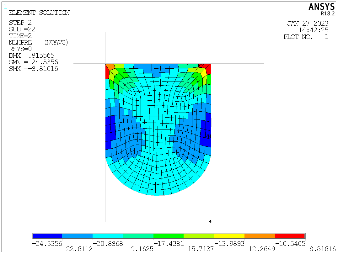
Hydrostatic pressure

Equivalent stress
