Applying a pure torque to a circular shaft should produce torsional deformation without bending. However, a finite element model may show an unexpected bending component even when the geometry, loading direction, and boundary conditions appear correct.
This article uses a simple circular shaft to demonstrate how an automatically generated mesh can introduce a small unbalanced resultant force. The behaviour is examined in both SolidWorks Simulation and ANSYS Mechanical, followed by several reliable workarounds.
1. Model description
Consider a circular shaft fixed at one end and subjected to a torque of T=10000Nm at the other end.
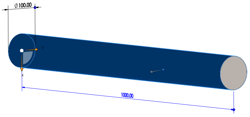
Figure 1. Shaft dimensions (unit: mm).
In SolidWorks Simulation, the torque is applied to the circular face (blue) at the loaded end. The cylindrical face (magenta) is selected as the reference geometry for defining the torque direction, as shown in Figure 2.
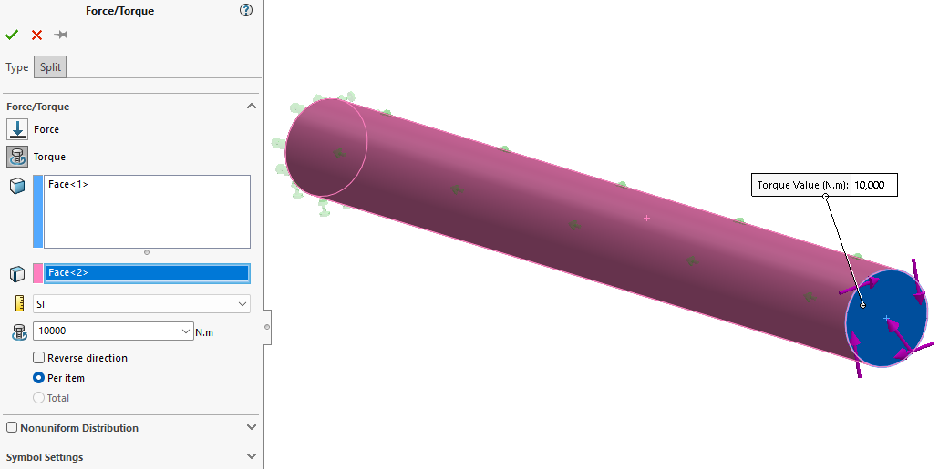
Figure 2. Applying the torque (taking ‘Face<2>’ i.e. the cylindrical face as a reference for torque direction).
A standard mesh is first generated using the default global element size (approximately 20mm).
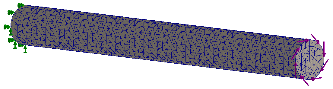
Figure 3. Standard mesh with the default element size.
Although the applied load is intended to represent pure torsion, the calculated deformation contains a noticeable bending component.
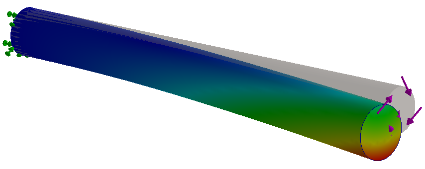
Figure 4. Unexpected bending obtained with the standard mesh.
2. Why does bending appear under a pure torque?
According to SolidWork documentation, ‘If you apply a torque to a face using as a reference for direction an axis that is not the axis of symmetry (or it is not parallel to the plane of symmetry), an unbalanced resultant force may appear in the results. Check that the magnitude of the unbalanced resultant force is small enough, so that it can be neglected’.
In this example, however, the axis of the selected cylindrical face is the longitudinal axis of the shaft. It is therefore also the axis of symmetry. The remaining issue is associated with how the torque is transferred to the finite element mesh.
Loads in a finite element model are ultimately applied through the nodes or equivalent nodal forces. A torque applied to a circular face is represented by a collection of nodal force components distributed over that face. Ideally, these forces should satisfy two conditions:
- The resultant moment should equal the specified torque;
- The resultant force should be zero in any direction.
When the nodes on the circular face are distributed symmetrically, both requirements can be satisfied naturally. However, an automatically generated mesh may not produce an axisymmetric nodal pattern. The equivalent nodal loads may reproduce the required torque while leaving a small residual force. This residual force introduces a bending component into a problem that should theoretically contain only torsion.
The issue is therefore not necessarily caused by an incorrect torque direction. It can arise from the discrete representation of the applied torque on a non-axisymmetric mesh.
3. Does a curvature-based mesh solve the problem?
A curvature based mesh generally represents circular boundaries more accurately than a standard mesh.
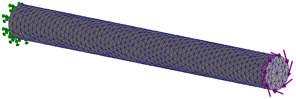
Figure 5. Curvature-based mesh with the default element size.
The resulting deformation shows that the bending component is significantly reduced.
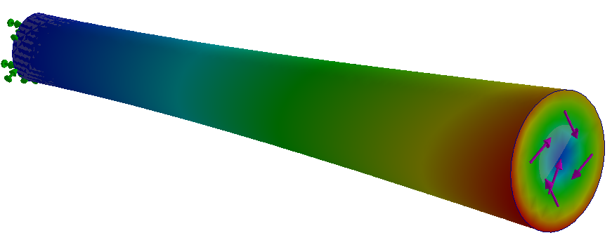
Figure 6. Reduced bending obtained with the curvature-based mesh.
However, closer inspection shows that the deformation is still not perfectly symmetric.
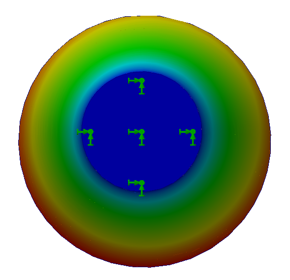
Figure 7. Bending remains when using curvature-based mesh.
The curvature-based mesher improves the geometric representation of the cylindrical surface, but it does not guarantee an axisymmetric distribution of nodes. It can therefore reduce the unbalanced force without necessarily eliminating it. Mesh refinement may produce further improvement, but refinement alone does not guarantee perfect symmetry. A finer asymmetric mesh remains asymmetric.
4. Workaround 1: Apply an additional Roller/Slider restraint
The Roller/Slider restraint can be used to specify that a planar face can move freely in its plane but cannot move in the direction normal to its plane. Most importantly, the face can shrink or expand under loading.
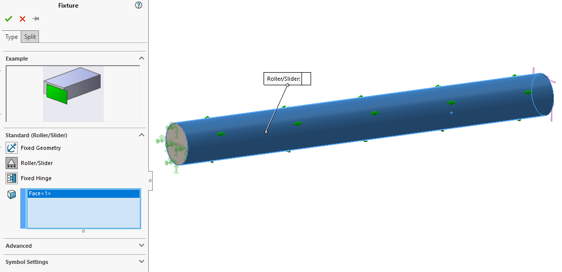
Figure 8. Adding Roller/Slider restraint to the cylindrical face.
With this additional restraint, the unexpected bending is eliminated.
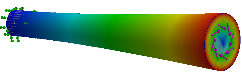
Figure 9. Bending is eliminated.
This approach is simple and computationally efficient. However, additional restraints should be used carefully. A numerical artefact should not be removed by imposing a constraint that changes the intended physical behaviour of the model. For a uniform circular shaft under pure torsion, radial displacement is not expected (apart from uniform expanding), so the additional restraint can be reasonable. For more complex geometries, non-circular sections, contact problems, or cases involving genuine transverse deformation, the same restraint could artificially stiffen the model.
5. Workaround 2: Use geometric and loading symmetry
A more systematic solution is to construct a symmetric fraction of the model. The full shaft can be divided into four bodies using two perpendicular planes passing through its longitudinal axis. In SolidWorks, this can be achieved using the Intersect feature (It is recommended that a new configuration is created for this purpose, so that the full geometry remains available in the original configuration).
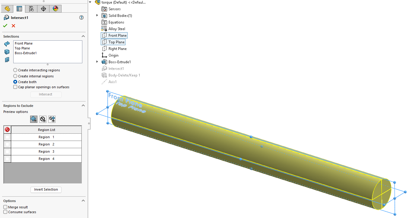
Figure 10. Dividing the shaft using the Intersect feature.
Three of the bodies are then removed, leaving a quarter shaft model.
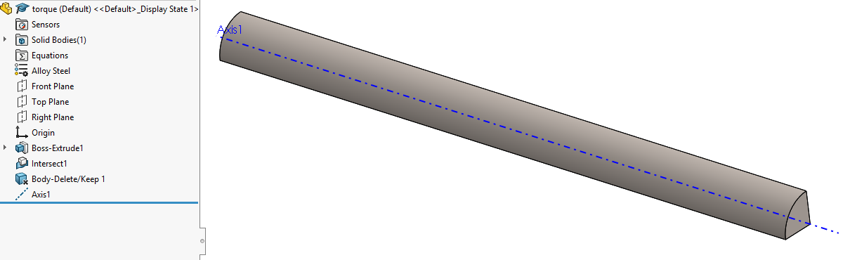
Figure 11. A quarter shaft model.
Cyclic Symmetry conditions are applied to the two cut faces.
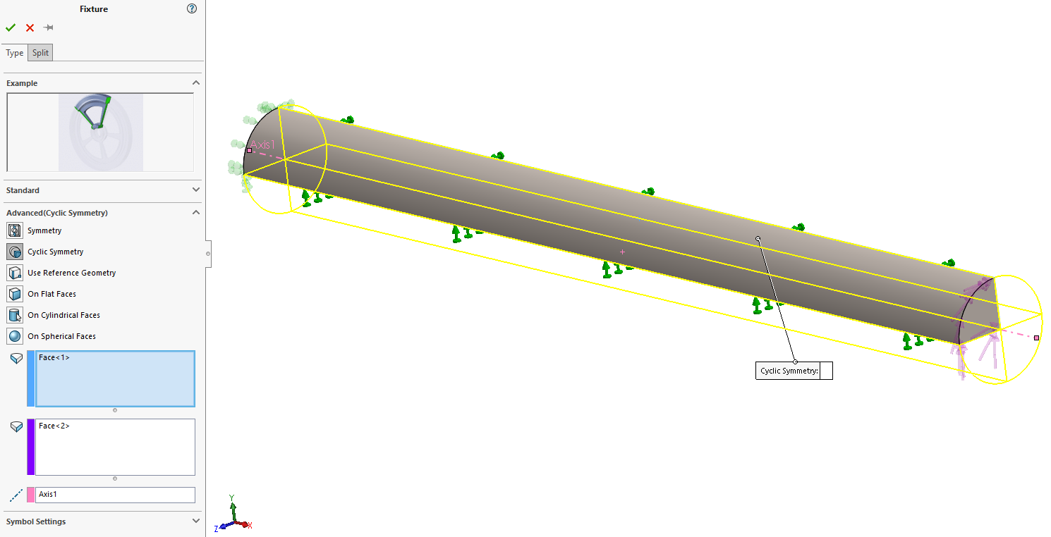
Figure 12. Adding additional restraint using Cyclic Symmetry.
A standard mesh can then be used.
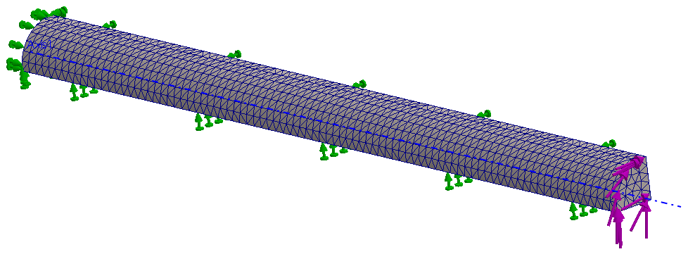
Figure 13. Standard mesh with default element size.
Because the geometry, mesh domain, restraints, and loading representation are now controlled by symmetry, the calculated response contains the expected torsional deformation.
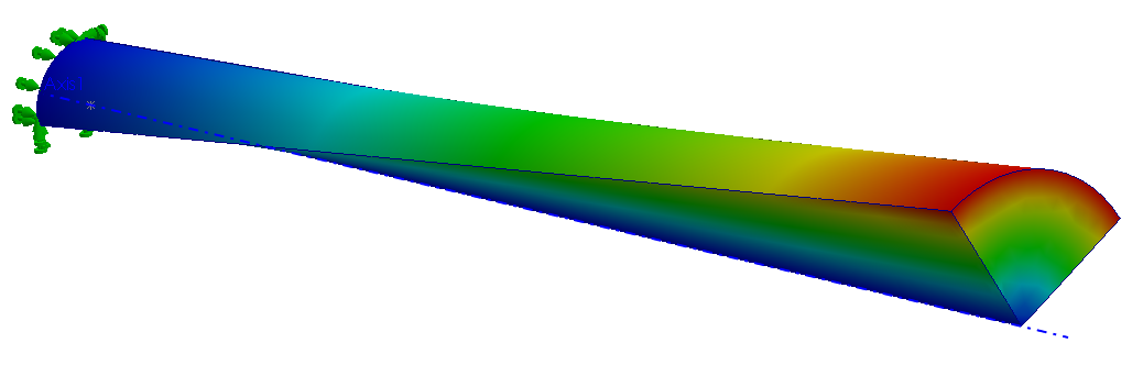
Figure 14. Deformation of the 1/4 model.
The complete shaft response can be displayed by expanding the symmetric result.
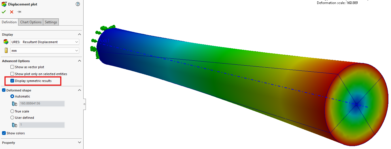
Figure 15. Deformation of the 1/4 model (displaying symmetric results).
This method avoids introducing an artificial radial restraint. It is therefore generally preferable when the geometry and loading genuinely satisfy the required symmetry conditions.
6. Comparison with Ansys Mechanical
The same shaft is analyzed in Ansys Mechanical using several meshing approaches. The element sizes are selected to be approximately comparable with the default element size used in SolidWorks Simulation.
6.1 Automatic mesh
The first model uses the automatic meshing method.
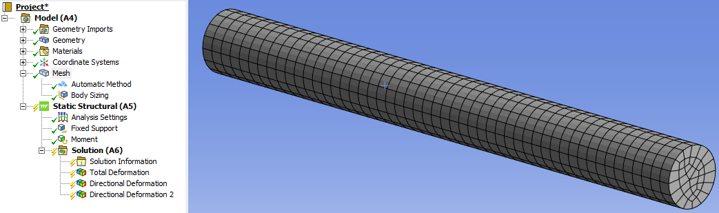
Figure 16. Using automatic mesh in ANSYS Mechanical.
The mesh on the circular end face is not perfectly axisymmetric. The total deformation appears predominantly torsional.
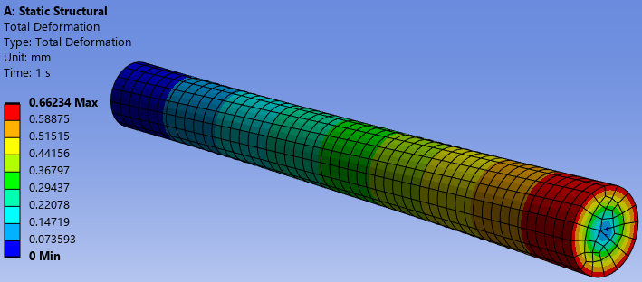
Figure 17. Total deformation.
However, the directional deformation along the Z axis (Figure 18) shows a small difference between the absolute values of the maximum and minimum results. For a perfectly symmetric torsional response, these extrema should have equal absolute values. Their small difference indicates that a minor bending component remains. This demonstrates an important postprocessing consideration. A small bending component may not be visually obvious in a total deformation plot. Directional deformation results can be more sensitive when assessing symmetry.
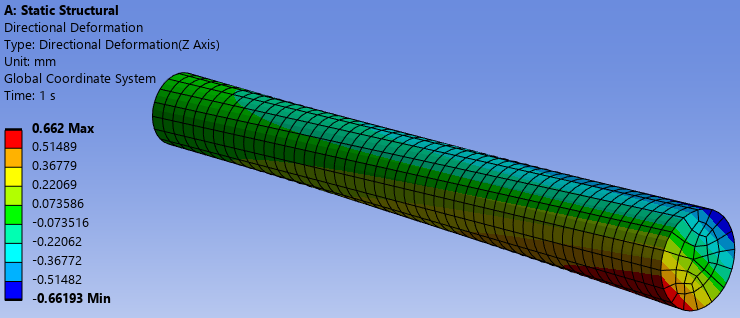
Figure 18. Directional deformation (Z axis).
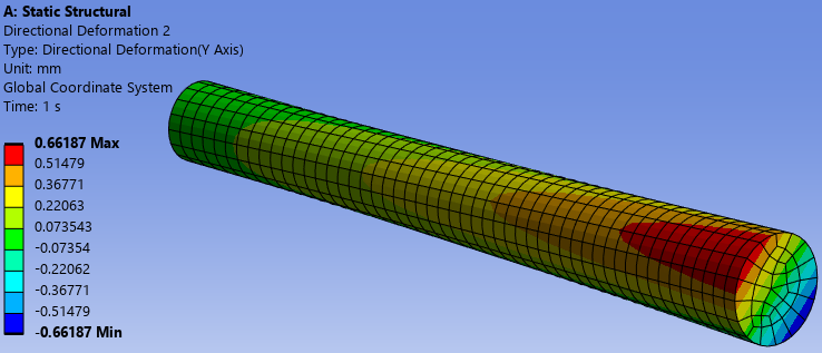
Figure 19. Directional deformation (Y axis).
6.2 Program Controlled sweep mesh
A sweep method is then selected using the Program Controlled algorithm.
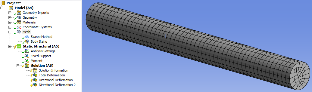
Figure 20. Using sweep mesh (Programe Controlled Algorithm).
For this geometry, the automatic meshing method already appears to prioritize a swept mesh. Consequently, explicitly selecting the Program Controlled sweep option produces essentially the same mesh and deformation results.
The use of swept elements alone does not guarantee that the nodes on the circular source and target faces will be distributed axisymmetrically.
6.3 Tetrahedral mesh
The shaft is also meshed using tetrahedral elements.
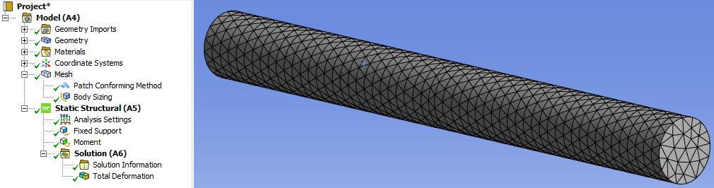
Figure 21. Tetrahedral mesh in ANSYS Mechanical.
The surface mesh on the circular end face remains nonaxisymmetric and is similar to the standard tetrahedral mesh generated in SolidWorks Simulation.
The total deformation does not show an obvious bending component.
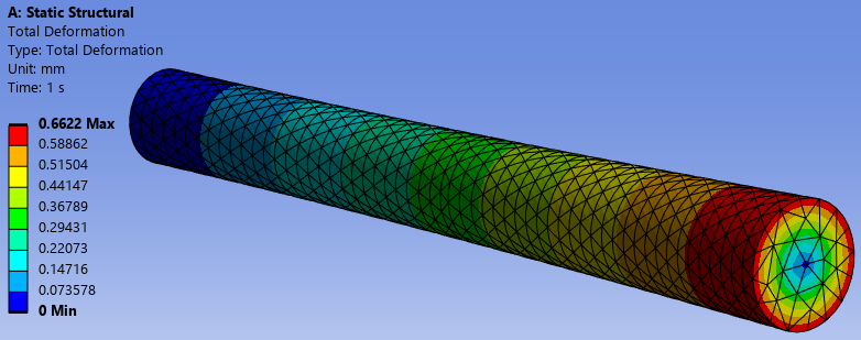
Figure 22. Total deformation.
Nevertheless, the directional deformation results reveal a small asymmetry.
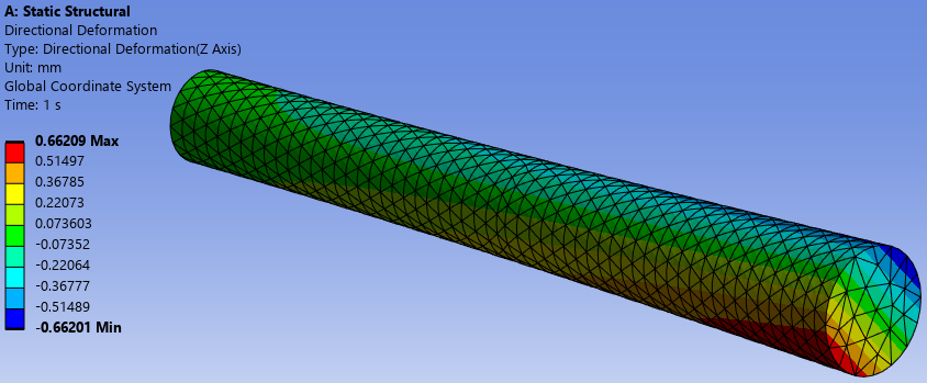
Figure 23. Directional deformation (Z axis).
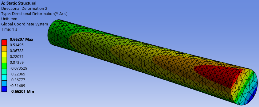
Figure 24. Directional deformation (Y axis).
This confirms that changing the element topology from swept elements to tetrahedral elements does not, by itself, resolve the underlying issue. The critical factor is the symmetry of the nodal distribution on the loaded face.
6.4 Sweep mesh using the Axisymmetric Algorithm
Finally, the sweep method is applied using the Axisymmetric Algorithm.
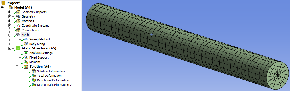
Figure 25. Sweep mesh generated using the Axisymmetric Algorithm.
This option produces an axisymmetric mesh on the source and target faces. The equivalent nodal forces used to represent the torque are therefore distributed symmetrically around the shaft axis.
The calculated total deformation shows the expected torsional response.
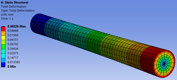
Figure 26. Total deformation.
More importantly, the maximum and minimum directional deformations have equal absolute values.
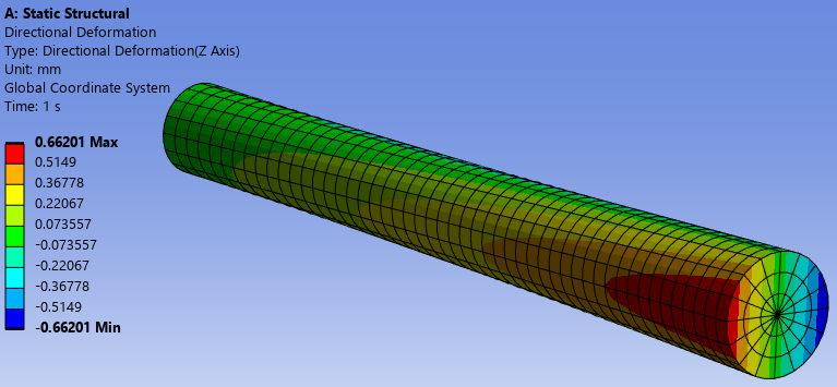
Figure 27. Directional deformation (Z axis).
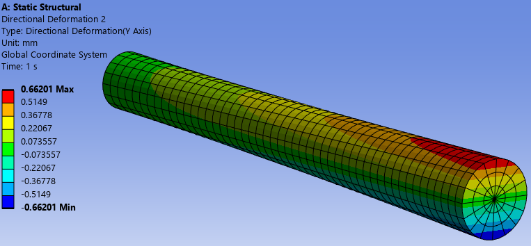
Figure 28. Directional deformation (Y axis).
The minor bending component observed with the other meshes is no longer present.
For this model, the axisymmetric sweep algorithm provides the most direct way to preserve the physical symmetry of the applied torque without adding supplementary restraints.
7. Practical lessons
The spurious bending under pure torque is not unique to SolidWorks Simulation, and it is not really a software defect. Both SolidWorks and Ansys show it with their default automatic meshers; the difference is how much control each gives you to fix it.
Some takeaways:
- Don’t assume a symmetric geometry guarantees a symmetric result. It is the mesh, not the geometry alone, that has to be symmetric for the load to resolve cleanly.
- A correctly specified torque may still produce a small unbalanced resultant force after discretization. Reproducing the correct resultant moment does not automatically guarantee that the resultant force is exactly zero.
- Total deformation plots are not always sufficient for identifying small asymmetric responses. Directional deformation or reaction forces should also be examined.
- Mesh refinement and mesh symmetry are different concepts. Refinement can reduce a discretization error, but a refined mesh is not necessarily symmetric.
- Additional restraints may suppress a numerical artefact, but they can also alter the structural response. Add them with discretion.
- Symmetry modelling or controlled mesh generation (i.e. sweep mesh in Ansys) is generally preferable when those approaches are compatible with the geometry and loading.

