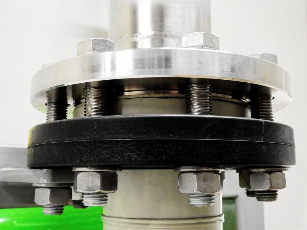

A typical bolted flange connection (see Fig.1) is modeled in this example.


Fig.1. The geometry of the model.
Only the 1/4 model is created due to symmetry. The challenges in this example are as follows:
- Complicated geometry.
- Applying pretension to bolts.
- Multiple load steps.
- Modeling contact.
It is worth mentioning that a special element Prentension179 is used to define preload in the bolt. The APDL of this example is attached:
FINISH
/CLEAR

!units: N, mm, MPa, 1E12kg/m^3
!geometric parameters
RAD_I=1250/2
RAD_PANI=705
RAD_O=2450/2
RAD_PANO=1830
RAD_B=180/2
M_BOLT=160
M_BH1=350+170+50
M_BH2=350+170+250
M_NUT=280/2
H_NUT=170
RAD_DRILL=2140/2
RAD_M=750+150
H_M=18
RAD_BI=1950/2
RAD_BO=2330/2
RAD_BH=5
F_RAD=45
FH_RAD=1855/2
R_FILLT=125
N=15
KEY_W=290
KEY_H=130
TH=200
FLANG_H1=350
FLANG_H2=350
H_SHAFT=350+490
H_SH=H_SHAFT+500
PI=ACOS(-1)
ELEMSIZE=60

!parameters for loads and boundaries
DISP_B=0.75
ZMAX=H_SH
F_EXT=22.9215E5*12
F_EEF=30.827E5*12
R_OUT=RAD_PANO
T_W=375
U_R=R_OUT-T_W

/PREP7
ET,1,185
MP,EX,1,2.06E5
MP,NUXY,1,0.29
MP,DENS,1,7.85E-9
MP,MU,2,0.15			!define the coefficient of friction as the 2nd material

!create keypoints
K,1,RAD_I,0,H_M
K,2,RAD_M,0,0
K,3,RAD_I+TH,0,0
K,4,RAD_O,0,0
K,5,RAD_O,0,FLANG_H1
K,6,RAD_M,0,FLANG_H1
K,7,RAD_I+TH,0,FLANG_H1
K,8,RAD_I+TH,0,H_SHAFT
K,9,RAD_I,0,H_SHAFT
K,10,RAD_I,0,FLANG_H1
K,11,RAD_M,0,H_M
K,12,RAD_I+TH,0,H_SH
K,13,RAD_I,0,H_SH
K,14,RAD_BI,0,RAD_BH
K,15,RAD_BO,0,RAD_BH
K,16,RAD_BI,0,0
K,17,RAD_BO,0,0
K,18,RAD_BI,0,FLANG_H1
K,19,RAD_BO,0,FLANG_H1
K,20,RAD_I+TH+F_RAD,0,FLANG_H1
K,21,FH_RAD,0,0
K,22,FH_RAD,0,FLANG_H1+H_SHAFT
K,23,FH_RAD,0,FLANG_H1

!create lines
L,8,20
L,20,5
L,21,22
LFILLT,1,2,125
LSTR,1,10
LSTR,10,9
LSTR,9,13
LSTR,13,12
LSTR,12,8
LSTR,8,9
LSTR,8,24
LSTR,1,11
LSTR,11,2
LSTR,2,21
LSTR,21,4
LSTR,4,5
LSTR,10,23
LSTR,5,23
LPTN,ALL				!Partitions lines

!generate areas
AL,7,8,9,10
AL,1,22,21,16,6,10
AL,5,11,12,13,18,16
A,5,4,21,23

!delete unwanted keypoints and lines
ALLSEL
LSLA
LSEL,INVERT
LDELE,ALL
ALLSEL
LSLA
KSLL
KSEL,INVERT
KDELE,ALL
ALLSEL

!generate volume by rotating area
CSYS,1				!activate Cylindrical coordinate system
KGEN,2,1,,,,N,,,0
L,1,3
VDRAG,ALL,,,,,,2

!Boolean operation
CSYS,0
CYL4,,,RAD_BI,,RAD_BO,,RAD_BH
VSBV,4,5
CYL4,RAD_DRILL,0,RAD_B,,,,FLANG_H1+100
CSYS,1
VGEN,,4,,,,N,,,,1
VSBV,6,4
WPROTA,N
CSYS,WP				!activate working plane
VSYMM,Y,ALL,,,,0,0
WPROTA,-N
CSYS,0
RECTNG,0,RAD_O+100,0,KEY_W/2
VSEL,ALL
ASLV
ASEL,INVERT
VEXT,ALL,,,0,0,KEY_H
ALLSEL
VPTN,ALL
VDELE,11,,,1
VDELE,12,,,1
VDELE,15,,,1
VDELE,16,,,1
VDELE,18,,,1
WPOFFS,0,KEY_W/2,0
WPROTA,,90
VSBW,ALL
WPCSYS,-1,0
WPOFFS,0,0,KEY_H
VSBW,ALL
WPCSYS,-1,0
CSYS,0
CYL4,,,RAD_BI,,RAD_BO,,FLANG_H1
VPTN,ALL
VDELE,33,,,1
WPOFFS,0,0,RAD_BH
VSBW,ALL
WPOFFS,0,0,-RAD_BH

!create the disc
CYLIND,RAD_PANI,RAD_PANO,0,-FLANG_H2,0,2*N
CYL4,RAD_DRILL,0,RAD_B,,,,FLANG_H2+100
CSYS,1
VGEN,,16,,,,N,-FLANG_H2,,,1
VSBV,15,16

!create groups of volume
VSEL,S,LOC,Z,0,H_SH+100
CM,SHAFT,VOLU
ALLSEL
VSEL,S,LOC,Z,0,-FLANG_H2-100
CM,PAN,VOLU
ALLSEL

!mesh
ESIZE,ELEMSIZE,0
MAT,1
ALLSEL
VSWEEP,ALL

!copy the shaft
ALLSEL
CMSEL,S,SHAFT,VOLU
ASLV
LSLA
KSLL
WPROT,2*N
CSYS,1
CMSEL,U,PAN,VOLU
VSEL,R,LOC,Y,N,2*N
CSYS,4
VSYMM,Y,ALL,,,,0,0
WPROT,N
VSEL,S,LOC,Z,0,H_SH+100
VSYMM,Y,ALL,,,,0,0
ESLV
NSLE
NUMMRG,NODE
NUMMRG,KP

!copy the disc
ALLSEL
WPCSYS,-1,0
CMSEL,S,PAN,VOLU
ASLV
LSLA
KSLL
WPROT,2*N
CSYS,4
VSYMM,Y,ALL,,,,0,0
WPROT,2*N
CSYS,1
VSEL,R,LOC,Y,2*N,4*N
CSYS,4
VSYMM,Y,ALL,,,,0,0
ALLSEL
WPCSYS,-1,0
VSEL,S,LOC,Z,0,-FLANG_H2-100
ASLV
LSLA
KSLL
ESLV
NSLE
NUMMRG,NODE
NUMMRG,KP

!create new groups of volume
VSEL,S,LOC,Z,0,H_SH+100
CM,SHAFT,VOLU
ALLSEL
VSEL,S,LOC,Z,0,-FLANG_H2-100
CM,PAN,VOLU
ALLSEL

!create bolts and nuts
CSYS,0
CYLIND,M_BOLT/2,,M_BH1,-M_BH2,0,360
RPR4,6,,,M_NUT,2*N,H_NUT
VGEN,,95,,,,,FLANG_H1,,,1
VGEN,2,95,,,,,-FLANG_H2-FLANG_H1-H_NUT,,0
CMSEL,U,PAN
CMSEL,U,SHAFT
VPTN,ALL
CM,B_TEMP,VOLU
VGEN,,ALL,,,RAD_DRILL,,,,,1
CSYS,1
VGEN,,ALL,,,,N,,,,1
MAT,1
ESIZE,ELEMSIZE/2
VSWEEP,ALL
VGEN,4,ALL,,,,N*2,,,0
CMSEL,U,B_TEMP,VOLU
VGEN,,ALL,,,,-N*2,,,,1
CM,BVOLU,VOLU
ALLSEL
CMSEL,S,B_TEMP,VOLU
VCLEAR,ALL
VDELE,ALL
ALLSEL

!create and mesh pretension sections (PRETS179 element)
PSMESH,1,B100,,VOLU,95,0,Z,0,,,,B_100
PSMESH,2,B200,,VOLU,116,0,Z,0,,,,B_200
PSMESH,3,B300,,VOLU,109,0,Z,0,,,,B_300

!create the contact between shaft and disc
CMSEL,S,SHAFT
ASLV
ASEL,R,LOC,Z,0
CM,AS_CON,AREA
ALLSEL
CMSEL,S,PAN
ASLV
ASEL,R,LOC,Z,0
CM,AP_TAR,AREA
ALLSEL
MAT,2
R,1
REAL,1
ET,3,TARGE170
ET,4,CONTA174
KEYOPT,4,9,0
CMSEL,S,AP_TAR
TYPE,3
NSLA,S,1
ESLN,S,0
ESURF,ALL
ALLSEL
CMSEL,S,AS_CON
TYPE,4
NSLA,S,1
ESLN,S,0
ESURF,ALL
ALLSEL

!create the contact between nut and FLANG_H1
CMSEL,S,BVOLU
ASLV
ASEL,R,LOC,Z,FLANG_H1
CM,AB1_CON,AREA
ALLSEL
CMSEL,S,SHAFT
ASLV
ASEL,R,LOC,Z,FLANG_H1
CSYS,1
ASEL,R,LOC,X,FH_RAD,RAD_O
CSYS,0
CM,ABS_TAR,AREA
ALLSEL
MAT,2
R,2
REAL,2
ET,5,170
ET,6,174
KEYOPT,6,9,0
CMSEL,S,ABS_TAR
TYPE,5
NSLA,S,1
ESLN,S,0
ESURF,ALL
ALLSEL
CMSEL,S,AB1_CON
TYPE,6
NSLA,S,1
ESLN,S,0
ESURF,ALL
ALLSEL

!create the contact between nut and FLANG_H2
CMSEL,S,BVOLU
ASLV
ASEL,R,LOC,Z,-FLANG_H2
CM,AB2_CON,AREA
ALLSEL
CMSEL,R,PAN
ASLV
ASEL,R,LOC,Z,-FLANG_H2
CM,ABP_TAR,AREA
ALLSEL
MAT,2
R,3
REAL,3
ET,7,170
ET,8,174
KEYOPT,8,9,0
CMSEL,S,ABP_TAR
TYPE,7
NSLA,S,1
ESLN,S,0
ESURF,ALL
ALLSEL
CMSEL,S,AB2_CON
TYPE,8
NSLA,S,1
ESLN,S,0
ESURF,ALL
ALLSEL

!settings for solution
/SOLU
ALLSEL
LSCLEAR,ALL
ANTYPE,0
AUTOTS,1
NSUBST,25,100,1
RESCONTROL,,NONE,NONE
OUTRES,ALL,ALL
EQSLV,PCG
TIME,15

!define symmetric boundaries
CSYS,1
ASEL,S,LOC,Y,0
DA,ALL,SYMM
ALLSEL
ASEL,S,LOC,Y,90
DA,ALL,SYMM
ALLSEL

!load step 1: apply pretension to three bolts
SLOAD,1,PL01,LOCK,DISP,DISP_B,1,2
SLOAD,2,PL01,LOCK,DISP,DISP_B,1,2
SLOAD,3,PL01,LOCK,DISP,DISP_B,1,2
!apply constraints
CMSEL,S,PAN
NSLV,R,1
NSEL,R,LOC,Z,0
CSYS,1
NSEL,R,LOC,X,U_R,R_OUT
D,ALL,ALL
ALLSEL
SBCTRAN
LSWRITE,1

!load step 2:  the displacement value resulting from the pretension force is locked
LSWRITE,2

!load step 3: apply loads
NSEL,S,LOC,Z,ZMAX-1,ZMAX+10
*GET,NLOAD,NODE,,COUNT
F,ALL,FZ,F_EXT/NLOAD,4
ALLSEL
LSWRITE,3
LSSOLVE,1,3,1

!post-processing
/POST1
SET,LAST
PLNSOL,S,EQV,0,1
CMSEL,S,BVOLU
ESLV,S
PLNSOL,S,EQV,0,1
CMSEL,S,PAN
ESLV,S
PLNSOL,S,EQV,0,1
CMSEL,S,SHAFT
ESLV,S
PLNSOL,S,EQV,0,1
ALLSEL
VSEL,S,,,94,96,1
VSEL,A,,,108,110,1
VSEL,A,,,115,117,1
ESLV,S
PLNSOL,S,EQV,0,1
ALLSEL
CMSEL,S,AS_CON
NSLA,S,1
ESLN,S,0
PLNSOL,S,EQV,0,1


Pingback: Contact Analysis of a Pipe-clamp Assembly | Xutao Sun