In nonlinear contact analysis, the initial geometric relationship between two surfaces can strongly influence both convergence and the physical meaning of the solution. Before external loading begins, Ansys evaluates the contact pair according to its initial gap or penetration and the contact detection region. A pair that is expected to transmit load but starts open may permit rigid-body motion before contact is established, while an unintended initial penetration can introduce artificial contact forces.
Interface Treatment (Figure 1) is the Ansys Mechanical control used to modify this effective initial contact condition without editing the underlying CAD geometry. Depending on the option selected, Mechanical can close an initial gap, ignore an initial penetration, or apply a user defined contact offset. These settings are available for nonlinear contact types such as Frictionless, Rough and Frictional contact.
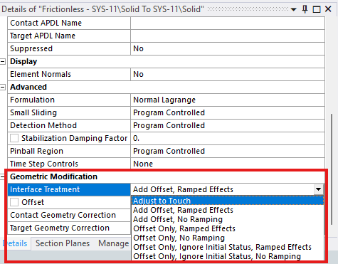
Figure 1. Interface Treatment.
In this post, a simple ball and plate model is used to examine three options: Adjust to Touch, Add Offset, No Ramping and Offset Only, No Ramping.
A ball-plate example
As shown in Figure 2, a ball is placed at the centre of a square plate. When gravity is not considered, the ball is just touching the plate and there is zero deformation. The four side faces of the plate are fixed. A downward displacement of 40mm is applied to the ball, as shown in Figure 3. As the ball moves downward, contact transfers load into the plate and produces large bending deformation.
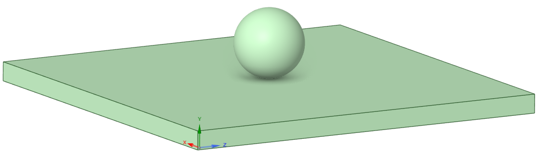
Figure 2. Geometry.
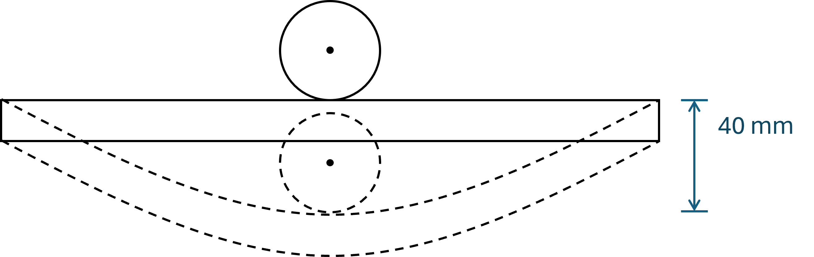
Figure 3. Before and after deformation.
Baseline simulation settings and results
A intentionally ‘stiff material’ with 1000MPa Young’s modulus is assigned to the ball, and a ‘soft material’ with 10MPA Young’s modulus is assigned to the plate, thus the contact-induced plate deformation can be more visible. Frictionless contact is defined between the ball and plate, with the ball designated as the contact side and the plate as the target side, as shown in Figure 4. Normal Lagrange contact formulation is used which enforces essentially zero contact penetration.
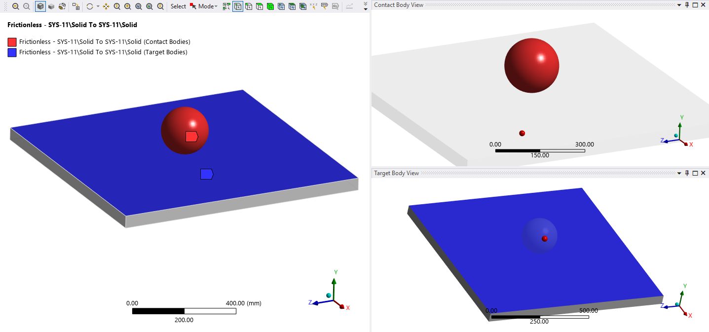
Figure 4. Contact body and target body.
MultiZone method is used to mesh the ball, and Sweep method is used to mesh the plate. A representative mesh is shown in Figure 5. The four side faces of the plate are completely fixed (Figure 6). A 40mm displacement is applied to the ball, with the direction opposite to the global Y direction (Figure 7). Because the imposed motion produces a substantial change in the geometry of the plate, Large Deflection is enabled.
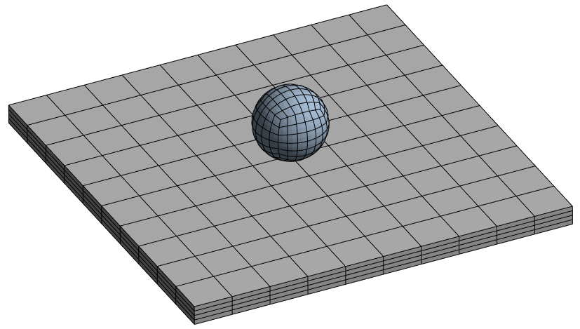
Figure 5. A representative mesh.
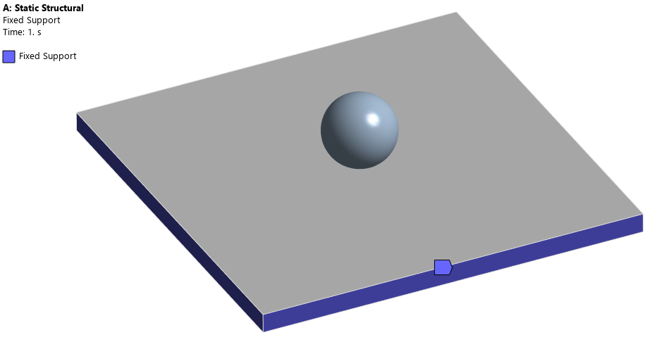
Figure 6. Fixed support on four side faces of the plate.
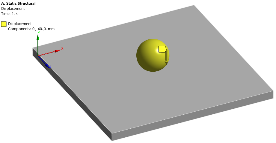
Figure 7. 40mm displacement (downward) on the ball.
The model is solved using a Static Structural analysis. The total displacement and von-Mises stress results are shown in Figure 8-Figure 11. The contact results at the end of the final substep are shown in Figure 12-Figure 14. From the results, the plate develops a bending dominated deformation field beneath the ball, while the much stiffer ball deforms only slightly. The maximum total deformation is approximately 40.06 mm, which is consistent with the prescribed 40 mm motion. The stress distribution is as expected. At the end of the simulation, the contact status is Sliding, which matches the physical status, and the maximum contact penetration is on the order of 10-7, effectively zero at the scale of this model, which is as expected with the Normal Lagrange formulation.
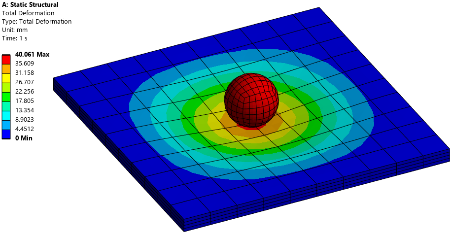
Figure 8. Total deformation.
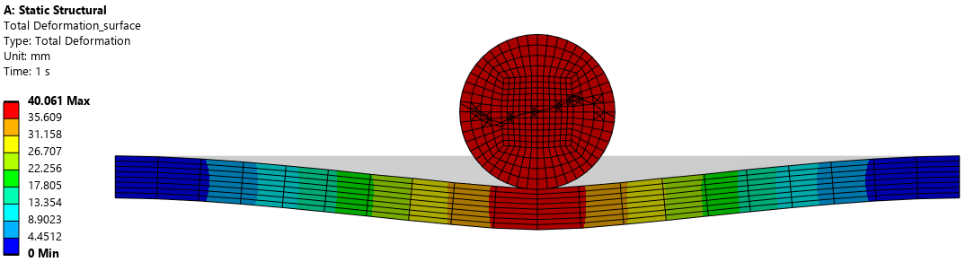
Figure 9. Total deformation (cross-sectional plot).
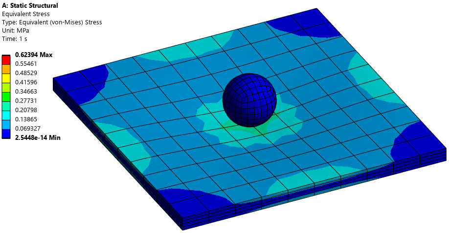
Figure 10. Von-Mises stress.
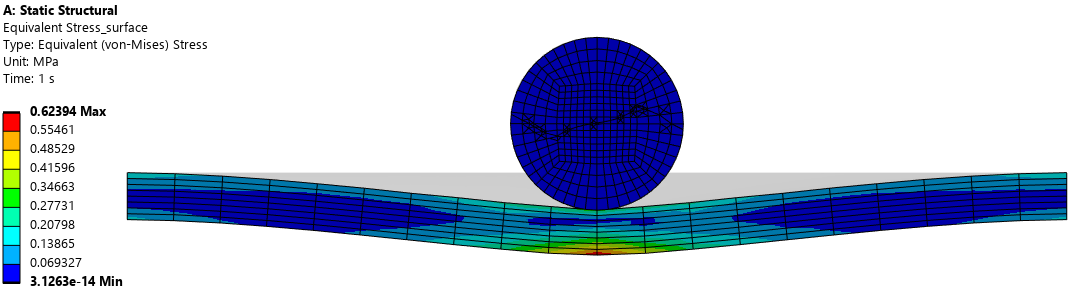
Figure 11. Von-Mises stress (cross-sectional plot).
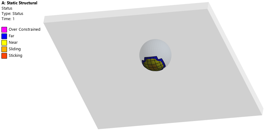
Figure 12. Contact status.
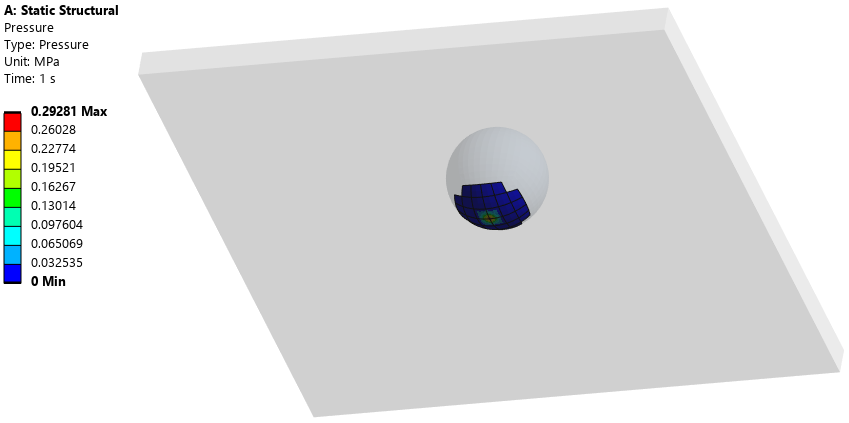
Figure 13. Contact pressure.
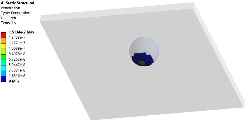
Figure 14. Contact penetration.
The baseline solution provides a reference for the following comparisons, where a 0.2 mm initial gap is introduced deliberately, and different Interface Treatment settings are used to determine how the solver interprets that gap. The objectives are to obtain a similar final response, and to understand how each option changes the effective initial contact condition.
Alternative setting 1: Adjust to Touch
According to AnsysHelp: Adjust to Touch – Any initial gaps are closed and any initial penetration is ignored creating an initial stress free state. Contact pairs are “just touching” as illustrated.
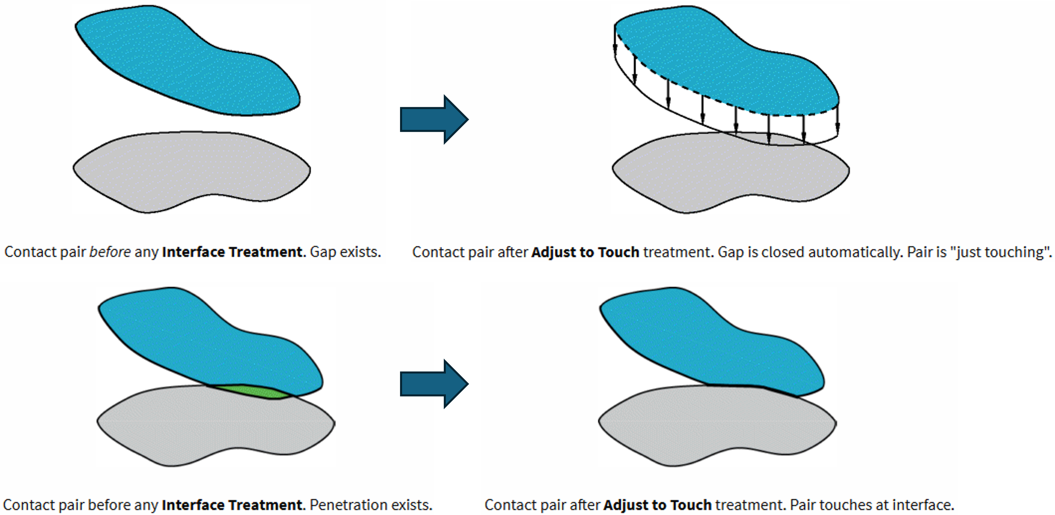
The main benefit of Adjust to Touch is that the underlying CAD geometry is not revised. Instead, the contact interface used by the solver is adjusted mathematically. The initial gap must be within the contact detection region. If the gap varies across the interface, the option closes the smallest gap, so other parts of the interface may remain open.
To test how Adjust to Touch works, a gap should be created between the ball and plate. Instead of revising the geometry in SpaceClaim, the gap can be created by using the Transforms functionality in Ansys Mechanical (right click Model -> Inset -> Transforms). As shown in Figure 15, the ball is transformed upward by 0.2mm, so that a gap of 0.2mm is created between the ball and plate. This effectively changes the model from Figure 3 to Figure 16. To achieve the same results as in the baseline simulation, Adjust to Touch should be selected in the Interface Treatment so that the 0.2mm gap can be closed mathematically. The boundary conditions, 40mm displacement, and other settings remain unchanged.
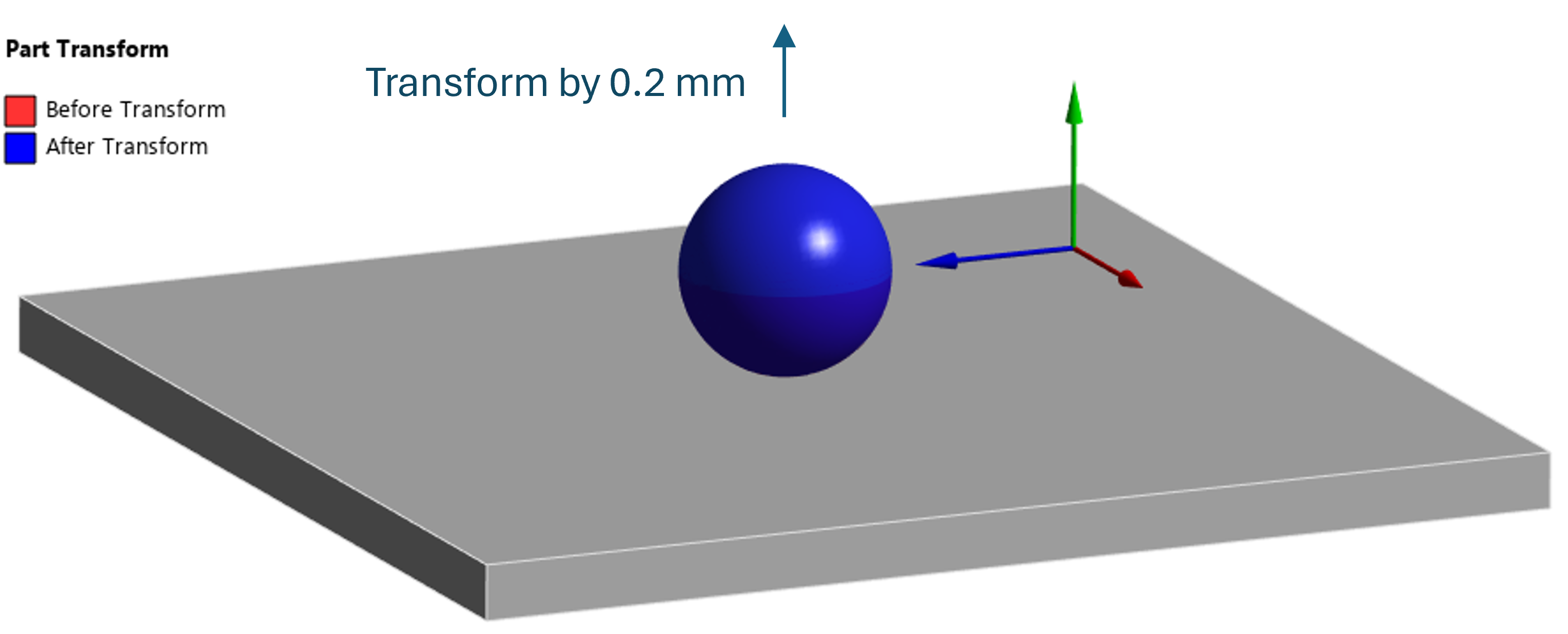
Figure 15. Transform the ball upward by 0.2mm.
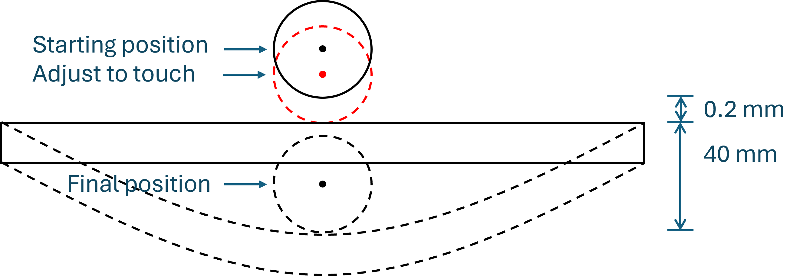
Figure 16. Model schematic.
After solving the model, the total deformation and von-Mises results are shown in Figure 17-Figure 18. The differences between the current results and those from the baseline simulation are negligible. This confirms that, for this simple model, Adjust to Touch removes the small initial gap from the contact kinematics without introducing an initial interference load. This setting is useful when a small gap is a modelling or meshing artefact and the intended physical condition is initial contact. It should not be used to remove a gap that represents a real physical clearance.
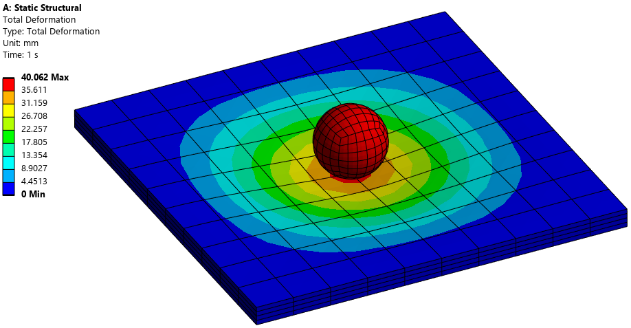
Figure 17. Total deformation.
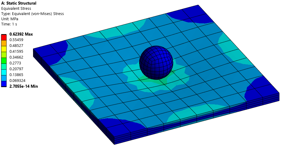
Figure 18. Von-Mises stress.
Alternative setting 2: Add Offset, No Ramping
According to AnsysHelp: Add Offset, Ramped Effects – Models the true contact gap/penetration plus adds in any user defined offset values. This setting is the closest to the default contact setting used in the Mechanical APDL except that the loading is ramped. Using this setting will not close gaps. Even a slight gap may cause bodies to fly apart. Should this occur, use a small contact offset to bring the bodies into initial contact. Note that this setting is displayed only for nonlinear contact and the ramping occurs over the first load step.
Add Offset, No Ramping – This is the default setting. This option is the same as Add Offset, Ramped Effects but loading is not ramped.
This is getting difficult to understand. We can keep the 0.2mm gap created in Alternative setting 1 and see what would happen if Add Offset, No Ramping is selected in the Interface Treatment and an offset value of 0.3mm is assigned. This effectively changes the model from Figure 3 to Figure 19. With the 0.3mm offset, the 0.2mm gap is closed and a 0.1mm displacement is initiated before the prescribed displacement. To achieve the same results as in the baseline simulation, the prescribed downward displacement is reduced from 40.0mm to 39.9mm. The boundary conditions and other settings are kept unchanged.
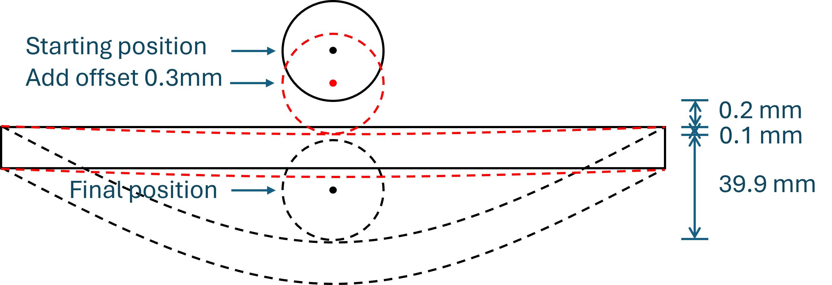
Figure 19. Model schematic.
After solving the model, the total deformation and von-Mises results are shown in Figure 20-Figure 21. The differences between the current results and those from the original simulation are still negligible. This verifies the understanding in Figure 19. More generally, Add Offset is appropriate when a known clearance or interference must be represented. Interference and shrink fit problems are common applications. For more difficult interference problems, the Ramped Effects variant can be useful because the offset effect is introduced gradually rather than applied in full at the start.
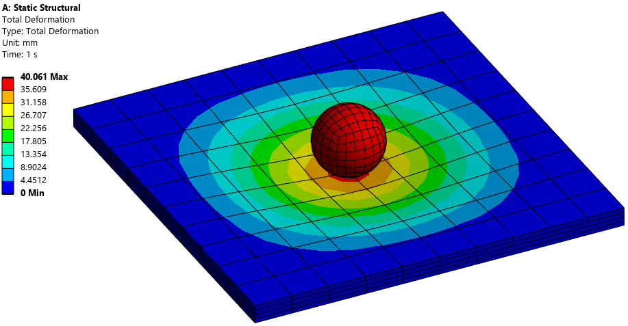
Figure 20. Total displacement.
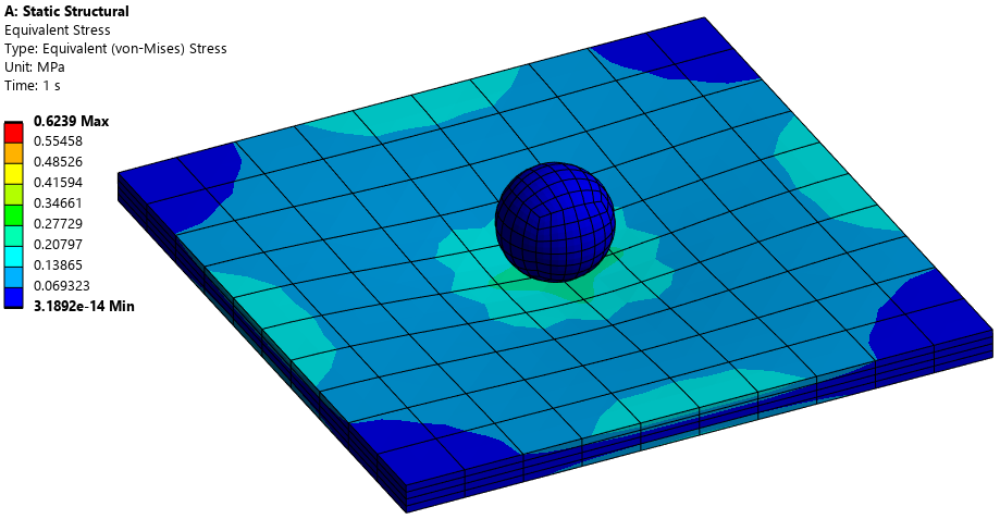
Figure 21. Von-Mises stress.
Alternative setting 3: Offset Only, No Ramping
According to AnsysHelp: Offset Only, Ramped Effects – Using this option, the application ignores any initial geometric penetrations if the initial status is in contact. If the initial status is near field, the application ignores the calculated initial penetration (Offset plus geometric gap), and applies only the remaining Offset value (remaining from Offset plus geometric gap calculation). All loading for this option is ramped.
Offset Only, No Ramping – This option performs the same actions as the Offset Only, Ramped Effects options except that loading is step-applied.
This is once again difficult to understand. To test how it works, only one change is made to Alternative setting 2, i.e. Offset Only, No Ramping is selected in the Interface Treatment and the offset value of 0.3mm is maintained. The new model schematic is shown in Figure 22, and it is almost the same as Figure 19 except that the name of the interface treatment is different. After solving the model, the total deformation and von-Mises results are shown in Figure 23-Figure 24. There is almost no change in the results, which indicates that ‘add offset’ and ‘offset only’ do not make any difference in this specific situation. However, from their definitions, Add Offset retains the geometric penetration, whereas Offset Only can disregard it before the specified Offset is applied. I expect there can be significant differences in some situations.
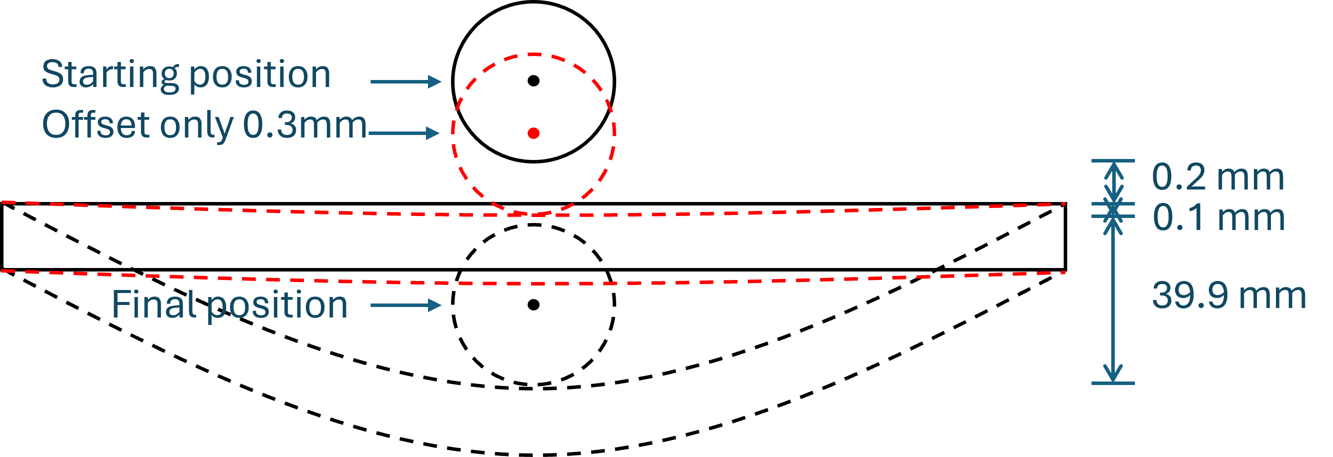
Figure 22. Model schematic.
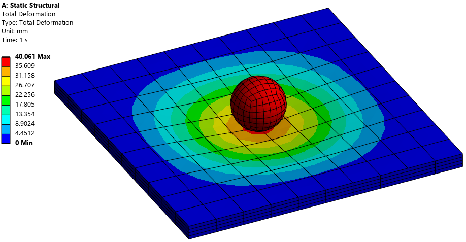
Figure 23. Total deformation.
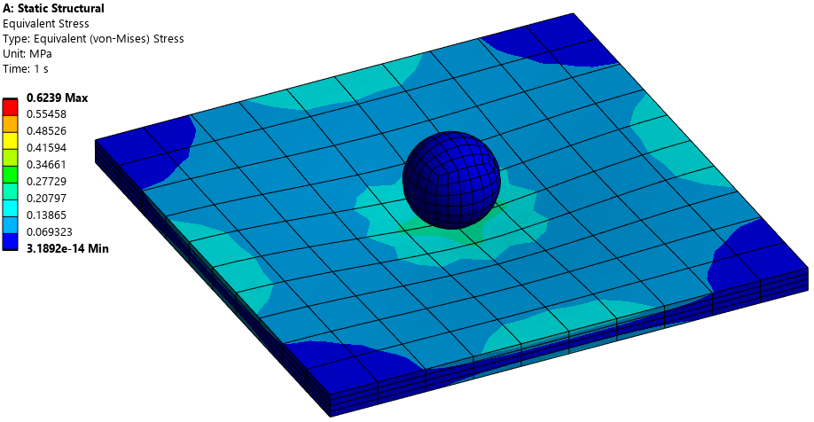
Figure 24. Von-Mises stress.
Takeaways & Applications
- Adjust to Touch is appropriate when surfaces are intended to begin just touching and a small geometric gap or penetration is not physically meaningful.
- Add Offset is appropriate when the actual geometric gap or penetration should be retained and an additional known clearance or interference is required.
- Offset Only changes how the existing geometric penetration is treated before the specified Offset is applied.
A practical workflow is to inspect Initial Information with the Contact Tool before solving (right click Connections -> Insert -> Contact Tool -> right click Initial Information -> Generate Initial Contact Results), confirm the geometric gap or penetration, verify that the intended surfaces lie within the contact detection region, and then choose the Interface Treatment that represents the assembly condition. After solving, contact status, gap, penetration, pressure, and reaction force should be reviewed together with the structural deformation and stress. A converged displacement or stress solution may not be sufficient evidence that the contact definition is physically meaningful.
When used carefully, Interface Treatment is a powerful way to represent small assembly gaps, intended initial contact, and interference conditions without rebuilding the geometry.
 Xutao Sun